13. Vertex Shaders and 3D
Until now our vertex shader has been almost boring.
It took four corners that were already in normalized device coordinates and passed them straight through, and all the interesting work happened in the fragment shader.
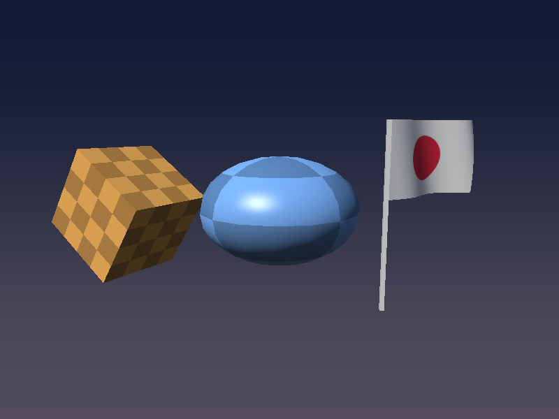
In this chapter the vertex shader finally gets a real job: we draw actual 3D objects (a cube, a squashed sphere and a waving flag), move them with matrices, project them with a camera, and even animate the geometry itself.
This is the chapter where the Linear Algebra series pays off.
Matrix–vector products, homogeneous coordinates, the inverse and the transpose, lookAt and the perspective matrix all show up again, this time running on the GPU for every single vertex.
Before you start: make a copy of your project folder.
Chapter 14 goes back to the shader playground from chapter 5, and chapter 15 continues from the code we write here, so it is handy to keep both versions.
13.1 What a vertex shader really does
The GPU runs the vertex shader once for every vertex it draws.
Each run gets that vertex's attributes (position, normal, UV and so on, the in variables with a layout(location = N)), and must write one thing: gl_Position, the vertex's position in clip space.
Anything else it writes to out variables is handed to the rasterizer, which interpolates it across the triangle and gives it to the fragment shader as in variables (we saw this in chapter 3).
The position we store in the mesh is in the object's own coordinate system.
To get it to clip space it goes through the same chain of spaces as in chapter 11 of the linear algebra series:
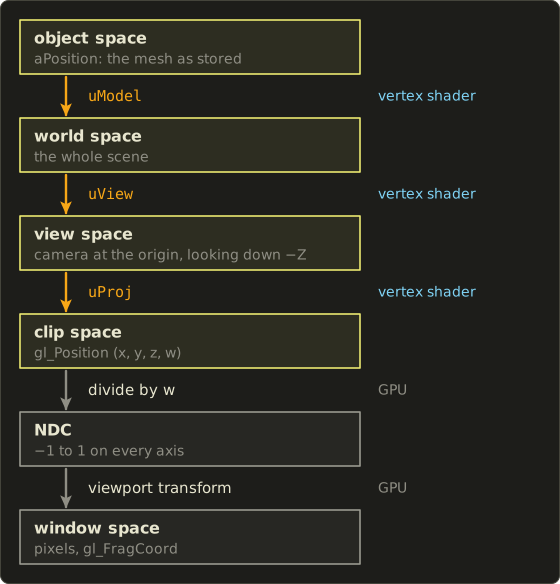
The three matrix steps are ours: we build the matrices in C and multiply in the vertex shader.
The last two steps are done by the GPU after the vertex shader: it divides by (the perspective divide from chapter 12) and maps NDC to pixels using the viewport we set with glViewport.
In one line of math, for a vertex at object-space position :
is the model matrix (object → world), the view matrix (world → view) and the projection matrix (view → clip).
The 1 in the fourth component is the homogeneous coordinate that lets translation work (linear algebra chapter 9).
Here is what we will have at the end of the chapter:
New files in this chapter:
| File | What it is |
|---|---|
include/matrix.h |
A tiny matrix library in C (header only) |
shader/vertex_mesh.glsl |
The 3D vertex shader (model, view, projection, normal matrix) |
shader/frag_phong.glsl |
Per-pixel Blinn-Phong lighting with UV patterns |
shader/vertex_gouraud.glsl, shader/frag_gouraud.glsl |
The same lighting, per vertex |
shader/vertex_flag.glsl |
Vertex animation: the waving flag |
shader/vertex_fullscreen.glsl, shader/frag_sky.glsl |
A background without any vertex buffer |
Xcode users: add the new files under shader/ to the project and to the "Copy Files" build phase, the same way as the existing shader files, or the app will not find them.
13.2 A tiny matrix library in C
The shader multiplies matrices, but somebody has to build them first.
For that we add a small header, include/matrix.h.
It follows the linear algebra series exactly: column vectors, right-handed coordinates, the camera looking down −Z, and column-major storage.
typedef struct {
  float m[16];
} Matrix4;

typedef struct {
  float m[9];
} Matrix3;

// element at row, col (0-based)
static inline float *mat4At(Matrix4 *a, int row, int col) {
  return &a->m[col * 4 + row];
}
Column-major means the 16 floats are stored one column after another: m[0..3] is the first column, m[4..7] the second, and so on.
That is the same layout as GLSL's mat4 (where m[col][row] is the indexing order, as we saw in chapter 2), so we can hand the array to OpenGL without rearranging anything.
The product of two matrices is the usual one from linear algebra chapter 7: the element in row , column is the dot product of row of with column of .
// r = a * b (b is applied first)
static inline Matrix4 mat4Multiply(Matrix4 a, Matrix4 b) {
  Matrix4 r;
  for (int col = 0; col < 4; col++) {
    for (int row = 0; row < 4; row++) {
      float sum = 0.0f;
      for (int k = 0; k < 4; k++) sum += a.m[k * 4 + row] * b.m[col * 4 + k];
      r.m[col * 4 + row] = sum;
    }
  }
  return r;
}
Translation puts the offset in the fourth column (linear algebra chapter 9), and the rotations are the ones from chapter 8:
static inline Matrix4 mat4Translate(float x, float y, float z) {
  Matrix4 r = mat4Identity();
  r.m[12] = x; // 4th column
  r.m[13] = y;
  r.m[14] = z;
  return r;
}

// rotation around the Y axis
static inline Matrix4 mat4RotateY(float angle) {
  float c = cosf(angle), s = sinf(angle);
  Matrix4 r = mat4Identity();
  *mat4At(&r, 0, 0) = c;  *mat4At(&r, 0, 2) = s;
  *mat4At(&r, 2, 0) = -s; *mat4At(&r, 2, 2) = c;
  return r;
}
The header also has mat4Identity, mat4Scale and mat4RotateX (same idea), plus the two camera matrices.
mat4LookAt builds the view matrix from an eye position, a target and an up vector, line for line like lookAt in linear algebra chapter 11 (small helpers vec3Sub, vec3Dot, vec3Cross and vec3Normalize do the vector work):
// view matrix: camera at eye looking at target
static inline Matrix4 mat4LookAt(Vector3 eye, Vector3 target, Vector3 up) {
  Vector3 f = vec3Normalize(vec3Sub(target, eye)); // forward
  Vector3 r = vec3Normalize(vec3Cross(f, up));     // right
  Vector3 u = vec3Cross(r, f);                     // up

  Matrix4 m = mat4Identity();
  *mat4At(&m, 0, 0) = r.x;  *mat4At(&m, 0, 1) = r.y;  *mat4At(&m, 0, 2) = r.z;
  *mat4At(&m, 1, 0) = u.x;  *mat4At(&m, 1, 1) = u.y;  *mat4At(&m, 1, 2) = u.z;
  *mat4At(&m, 2, 0) = -f.x; *mat4At(&m, 2, 1) = -f.y; *mat4At(&m, 2, 2) = -f.z;
  *mat4At(&m, 0, 3) = -vec3Dot(r, eye);
  *mat4At(&m, 1, 3) = -vec3Dot(u, eye);
  *mat4At(&m, 2, 3) = vec3Dot(f, eye);
  return m;
}
mat4Perspective is the OpenGL perspective matrix from linear algebra chapter 12, with , aspect ratio , near plane and far plane :
// perspective (OpenGL: NDC z from -1 to 1), fovY = vertical field of view in radians
static inline Matrix4 mat4Perspective(float fovY, float aspect, float n, float f) {
  float t = 1.0f / tanf(fovY * 0.5f);
  Matrix4 m = { { 0 } };
  *mat4At(&m, 0, 0) = t / aspect;
  *mat4At(&m, 1, 1) = t;
  *mat4At(&m, 2, 2) = -(f + n) / (f - n);
  *mat4At(&m, 2, 3) = -(2.0f * f * n) / (f - n);
  *mat4At(&m, 3, 2) = -1.0f;
  return m;
}
Sending a matrix to the shader
Matrices go to the shader as uniforms, with glUniformMatrix4fv (and glUniformMatrix3fv for 3×3):
// set a matrix uniform (already column-major, so transpose = GL_FALSE)
void setMat4(GLuint program, const char *name, Matrix4 m) {
  glUniformMatrix4fv(glGetUniformLocation(program, name), 1, GL_FALSE, m.m);
}

void setMat3(GLuint program, const char *name, Matrix3 m) {
  glUniformMatrix3fv(glGetUniformLocation(program, name), 1, GL_FALSE, m.m);
}
The third argument asks "should OpenGL transpose this for you?".
OpenGL expects column-major data, and ours already is, so the answer is GL_FALSE.
If you store matrices row-major (many C++ math libraries and DirectX-style code do), you would pass GL_TRUE instead, or transpose them yourself.
Getting this wrong does not crash anything; your objects just fly off in strange directions, because the translation ends up in the bottom row where it multiplies instead.
A worked example: one vertex all the way to the screen
Let me follow one corner of the cube by hand, so the numbers are not magic.
The cube corner is in object space, the model matrix only moves the cube left and up by , and (to keep the numbers simple) the camera sits at looking at the origin, so the view matrix is just a translation by .
The projection uses fovY = 50°, , , :
World space: .
View space: , so the point is 4.5 units in front of the camera (in front means negative z).
Clip space, row by row:
That is what the vertex shader writes to gl_Position.
Then the GPU divides by : NDC .
Finally the viewport maps to pixels: and (from the bottom of the window).
The of 0.9575 goes into the depth buffer, which we will need in a moment.
In the real program the camera is at and looks slightly down at , which makes the view matrix a bit less pretty, but the steps are the same.
13.3 A cube mesh
A cube has 8 corners, but we store 24 vertices: 4 for each of the 6 faces.
The reason is the normal.
A vertex is the whole bundle of attributes, not just a position, and the corner where three faces meet needs three different normals (one per face) to get flat, sharp-edged faces.
So each face gets its own 4 vertices.
Every vertex is 8 floats: position (3), normal (3), UV (2).
A small helper uploads such an array and sets up the three attributes, at locations 0, 1 and 2:
// a mesh: vertex array object and number of indices
typedef struct {
  GLuint vao, vbo, ebo;
  GLsizei indexCount;
} Mesh;

// vertex format: position (3), normal (3), UV (2) = 8 floats
#define VERTEX_FLOATS 8

Mesh createMesh(const float *vertices, int vertexCount, const GLuint *indices, int indexCount) {
  Mesh mesh;
  mesh.indexCount = indexCount;
  glGenVertexArrays(1, &mesh.vao);
  glGenBuffers(1, &mesh.vbo);
  glGenBuffers(1, &mesh.ebo);

  glBindVertexArray(mesh.vao);
  glBindBuffer(GL_ARRAY_BUFFER, mesh.vbo);
  glBufferData(GL_ARRAY_BUFFER, vertexCount * VERTEX_FLOATS * sizeof(float), vertices, GL_STATIC_DRAW);
  glBindBuffer(GL_ELEMENT_ARRAY_BUFFER, mesh.ebo);
  glBufferData(GL_ELEMENT_ARRAY_BUFFER, indexCount * sizeof(GLuint), indices, GL_STATIC_DRAW);

  // attributes: position (location 0), normal (location 1), UV (location 2)
  GLsizei stride = VERTEX_FLOATS * sizeof(float);
  glVertexAttribPointer(0, 3, GL_FLOAT, GL_FALSE, stride, (void *)0);
  glEnableVertexAttribArray(0);
  glVertexAttribPointer(1, 3, GL_FLOAT, GL_FALSE, stride, (void *)(3 * sizeof(float)));
  glEnableVertexAttribArray(1);
  glVertexAttribPointer(2, 2, GL_FLOAT, GL_FALSE, stride, (void *)(6 * sizeof(float)));
  glEnableVertexAttribArray(2);

  glBindVertexArray(0);
  return mesh;
}

void drawMesh(const Mesh *mesh) {
  glBindVertexArray(mesh->vao);
  glDrawElements(GL_TRIANGLES, mesh->indexCount, GL_UNSIGNED_INT, 0);
}
(destroyMesh deletes the three objects again at the end.)
Instead of typing 24 × 8 numbers, I describe each face by its normal and two directions (right) and (up) that lie in the face.
The four corners are then , for a cube of side 1 centred on the origin.
// cube (side 1, centred on the origin): 4 vertices per face (each face has its own normal)
Mesh createCube(void) {
  // per face: normal n, right u, up v (u x v = n, so counter-clockwise seen from outside)
  const float faces[6][9] = {
    {  1, 0, 0,   0, 0, -1,   0, 1, 0 }, // +X
    { -1, 0, 0,   0, 0, 1,    0, 1, 0 }, // -X
    {  0, 1, 0,   1, 0, 0,    0, 0, -1 }, // +Y
    {  0, -1, 0,  1, 0, 0,    0, 0, 1 }, // -Y
    {  0, 0, 1,   1, 0, 0,    0, 1, 0 }, // +Z
    {  0, 0, -1,  -1, 0, 0,   0, 1, 0 }, // -Z
  };
  const float corners[4][2] = { { -1, -1 }, { 1, -1 }, { 1, 1 }, { -1, 1 } };

  float vertices[24 * VERTEX_FLOATS];
  GLuint indices[36];
  for (int f = 0; f < 6; f++) {
    const float *n = faces[f], *u = faces[f] + 3, *v = faces[f] + 6;
    for (int c = 0; c < 4; c++) {
      float s = corners[c][0], t = corners[c][1];
      float *out = &vertices[(f * 4 + c) * VERTEX_FLOATS];
      for (int k = 0; k < 3; k++) out[k] = 0.5f * (n[k] + s * u[k] + t * v[k]); // position
      for (int k = 0; k < 3; k++) out[3 + k] = n[k];                            // normal
      out[6] = 0.5f * (s + 1.0f);                                               // UV
      out[7] = 0.5f * (t + 1.0f);
    }
    GLuint base = f * 4;
    GLuint quad[6] = { base, base + 1, base + 2, base + 2, base + 3, base };
    memcpy(&indices[f * 6], quad, sizeof(quad));
  }
  return createMesh(vertices, 24, indices, 36);
}
The order of and is not random.
I chose them so that (the cross product from linear algebra chapter 5).
For the +X face, for example, .
With that rule, the corners go counter-clockwise when you look at the face from outside, and OpenGL uses that winding order to tell the front of a triangle from its back.
We will use it for back-face culling below.
13.4 The first 3D vertex shader
Here is the first version of shader/vertex_mesh.glsl.
It reads all three attributes, but for now only passes the normal on:
#version 450 core

layout(location = 0) in vec3 aPosition;
layout(location = 1) in vec3 aNormal;
layout(location = 2) in vec2 aUv;

out vec3 vNormal;

uniform mat4 uModel;
uniform mat4 uView;
uniform mat4 uProj;

void main() {
  vNormal = aNormal;
  gl_Position = uProj * uView * uModel * vec4(aPosition, 1.0);
}
vec4(aPosition, 1.0) turns the 3D position into a homogeneous point with .
A direction would get so that translation does not affect it; we will use that idea for normals soon.
In GLSL, * between a mat4 and a vec4 is a real matrix–vector product (not component-wise like vec4 * vec4), and between two mat4 it is the matrix product.
uProj * uView * uModel * v is evaluated from left to right, like any chain of * in C, so the GPU first computes uProj * uView (a 4×4 times 4×4 product, 64 multiplications), then times uModel (another 64), and only then times the vector (16).
Writing uProj * (uView * (uModel * v)) gives exactly the same result (matrix multiplication is associative) but only does three matrix–vector products, 48 multiplications.
For a cube that does not matter at all, and the driver's compiler may even rearrange it for you, but it is a good habit, and it is the reason real engines usually compute uProj * uView * uModel once on the CPU and send a single uMVP matrix.
The final version below keeps the world-space position separately, because the lighting needs it.
For the fragment shader, a trick from chapter 5: show the data as a colour.
A normal has components from −1 to 1, so maps it to 0 to 1:
#version 450 core

in vec3 vNormal;
out vec4 out_color;

void main() {
  // normal (-1..1) as a colour (0..1)
  out_color = vec4(normalize(vNormal) * 0.5 + 0.5, 1.0);
}
On the C side we build the camera every frame and draw the cube:
    // camera: view matrix and projection matrix
    Vector3 eye = { { 0.0f, 1.0f, 5.0f } };
    Vector3 target = { { 0.0f, 0.1f, 0.0f } };
    Vector3 up = { { 0.0f, 1.0f, 0.0f } };
    Matrix4 view = mat4LookAt(eye, target, up);
    float aspect = gHeight > 0 ? (float)gWidth / (float)gHeight : 1.0f;
    Matrix4 proj = mat4Perspective(50.0f * PI / 180.0f, aspect, 0.1f, 100.0f);

    glUseProgram(program);
    setMat4(program, "uView", view);
    setMat4(program, "uProj", proj);
    Matrix4 model = mat4Multiply(mat4RotateY(time * 0.7f + 0.5f), mat4RotateX(0.5f));
    model = mat4Multiply(mat4Translate(0.0f, 0.1f, 0.0f), mat4Multiply(model, mat4Scale(1.6f, 1.6f, 1.6f)));
    setMat4(program, "uModel", model);
    drawMesh(&cube);
(PI is a #define at the top of main.c, because M_PI is not part of standard C and MSVC does not define it by default.)
The aspect ratio uses the framebuffer size from chapter 5, so the cube stays a cube when you resize the window or run on a Retina display.
The depth buffer
Run that and you get the left picture:
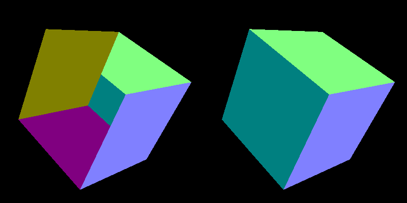
Something is very wrong.
Triangles are simply drawn in the order they come in the index buffer, and a later triangle paints over an earlier one, even if it is behind it.
Our faces are stored in the order +X, −X, +Y, −Y, +Z, −Z, so the −Y and −Z faces on the far side are drawn last and cover the front faces.
The fix is the depth buffer (Z-buffer): a second image with one depth value per pixel.
Remember the of 0.9575 from the worked example: the GPU maps NDC to a depth between 0 and 1 and, with the depth test on, only keeps a fragment if it is closer than what is already stored in that pixel.
  // depth test and back-face culling
  glEnable(GL_DEPTH_TEST);
  glEnable(GL_CULL_FACE);
  glCullFace(GL_BACK);
  glFrontFace(GL_CCW);
And every frame the depth buffer has to be cleared together with the colour, or last frame's depths would block everything:
glClear(GL_COLOR_BUFFER_BIT | GL_DEPTH_BUFFER_BIT);
GL_CULL_FACE is a bonus: triangles whose winding looks clockwise on screen are facing away from the camera, so the GPU throws them away before rasterizing.
For a closed mesh like a cube you can never see those anyway, so this halves the work.
glFrontFace(GL_CCW) says counter-clockwise is the front, which is why the winding of our faces mattered.
Now the cube looks right (the right picture above): +Y is green , +X would be pink-red, and −X, the left face, is teal .
13.5 Normals and the normal matrix
For lighting we need the normal in world space, like the light direction and the camera position.
The obvious idea is to multiply it by the model matrix, mat3(uModel) * aNormal (the mat3(...) constructor takes the upper-left 3×3 of a mat4, dropping the translation, which a direction must ignore).
That works for rotations and uniform scaling, but breaks as soon as you scale differently along different axes:
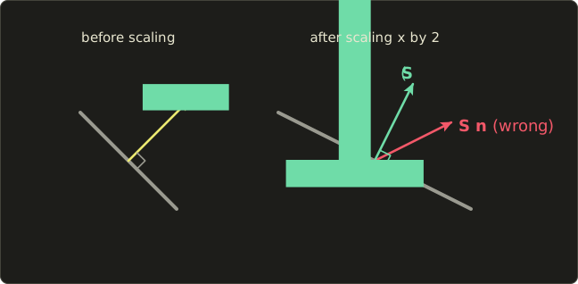
What the formula is
The correct matrix for normals is the inverse transpose of the upper-left 3×3 part of the model matrix:
Why it works
A normal is defined by one property: it is perpendicular to every tangent of the surface, .
Tangents are differences between nearby points on the surface, so they transform like positions: .
We want some matrix so that the new normal is still perpendicular to the new tangent:
If , this is for every tangent, which is exactly what we want.
So , that is (inverse from linear algebra chapter 10, transpose from chapter 7).
Two special cases explain why the naive version often seems fine:
- A pure rotation has , so : the normal matrix is the rotation itself.
- A uniform scale by gives : only the length changes, and we normalize anyway.
A worked example
Our sphere is squashed with .
Take the point on the unit sphere.
Its normal is the same vector, , and one tangent is (check: ).
After squashing, the tangent becomes .
The naive normal is , and
so it is not perpendicular to the surface any more.
For a diagonal matrix, the inverse transpose is just the reciprocals on the diagonal, , so the correct normal is , and
Here is the difference on screen (the lighting shader comes in the next section):
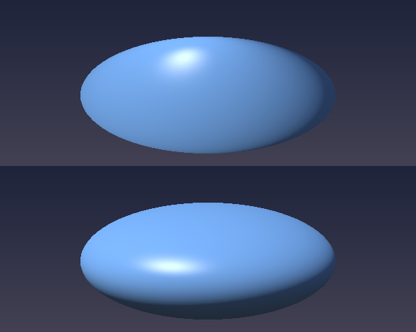
The top one is shaded like a round sphere that was painted onto a flat shape: the highlight sits too high and the bottom is still lit.
The bottom one is shaded like what it really is, a flat pebble: the light hits the broad top and the underside is dark.
Computing it in C
GLSL has inverse() and transpose() (for mat2, mat3, mat4), so transpose(inverse(mat3(uModel))) would work in the shader.
But it would be recomputed for every vertex although it is the same for the whole object, so I compute it once per object in C.
There is a neat shortcut: the inverse is the adjugate (the transposed cofactor matrix) divided by the determinant, so the inverse transpose is the cofactor matrix divided by the determinant, and we never have to transpose anything.
// normal matrix: inverse transpose of the upper-left 3x3 of the model matrix
// inverse transpose = cofactor matrix / determinant, so we compute the cofactors directly
static inline Matrix3 mat3NormalMatrix(Matrix4 a) {
  // elements of the upper-left 3x3 (row, column)
  float m00 = a.m[0], m10 = a.m[1], m20 = a.m[2];
  float m01 = a.m[4], m11 = a.m[5], m21 = a.m[6];
  float m02 = a.m[8], m12 = a.m[9], m22 = a.m[10];

  // cofactors
  float c00 = m11 * m22 - m12 * m21, c01 = m12 * m20 - m10 * m22, c02 = m10 * m21 - m11 * m20;
  float c10 = m02 * m21 - m01 * m22, c11 = m00 * m22 - m02 * m20, c12 = m01 * m20 - m00 * m21;
  float c20 = m01 * m12 - m02 * m11, c21 = m02 * m10 - m00 * m12, c22 = m00 * m11 - m01 * m10;

  float det = m00 * c00 + m01 * c01 + m02 * c02;
  float inv = det != 0.0f ? 1.0f / det : 0.0f;

  // result (row i, column j) = c_ij / det, stored column-major
  Matrix3 r;
  r.m[0] = c00 * inv; r.m[1] = c10 * inv; r.m[2] = c20 * inv;
  r.m[3] = c01 * inv; r.m[4] = c11 * inv; r.m[5] = c21 * inv;
  r.m[6] = c02 * inv; r.m[7] = c12 * inv; r.m[8] = c22 * inv;
  return r;
}
The determinant is the cofactor expansion along the first row (linear algebra chapter 10).
I checked this function against a numerical inverse transpose with a random rotation, scale and translation; the largest difference was below .
The final vertex shader passes the world-space position, the normal and the UV:
#version 450 core

layout(location = 0) in vec3 aPosition;
layout(location = 1) in vec3 aNormal;
layout(location = 2) in vec2 aUv;

out vec3 vWorldPos; // position in world space
out vec3 vNormal;   // normal in world space
out vec2 vUv;

uniform mat4 uModel;        // object space -> world space
uniform mat4 uView;         // world space -> view space
uniform mat4 uProj;         // view space -> clip space
uniform mat3 uNormalMatrix; // for normals (inverse transpose of the model matrix)

void main() {
  vec4 worldPos = uModel * vec4(aPosition, 1.0);
  vWorldPos = worldPos.xyz;
  vNormal = uNormalMatrix * aNormal;
  vUv = aUv;
  gl_Position = uProj * (uView * worldPos);
}
Notice the brackets in the last line: we already have worldPos, so two matrix–vector products finish the job.
13.6 Lighting in world space
The fragment shader is the Blinn-Phong model from chapter 9, with the hemisphere ambient from chapter 10 and gamma correction at the end, now in world space: the normal, the light direction and the camera position all live in the same space, which is the one rule lighting really cares about.
#version 450 core

in vec3 vWorldPos;
in vec3 vNormal;
in vec2 vUv;
out vec4 out_color;

uniform vec3 uColor;     // surface colour (linear)
uniform vec3 uLightDir;  // direction from the surface towards the light (world space)
uniform vec3 uCameraPos; // camera position (world space)
uniform int uPattern;    // 0: plain, 1: checker, 2: Japanese flag

// surface colour from the UVs
vec3 albedo() {
  if (uPattern == 1) {
    vec2 cell = floor(vUv * 4.0);
    float checker = mod(cell.x + cell.y, 2.0);
    return uColor * mix(0.55, 1.0, checker);
  }
  if (uPattern == 2) {
    vec2 p = (vUv - 0.5) * vec2(1.4 / 0.9, 1.0); // aspect ratio of the flag
    float disc = 1.0 - smoothstep(0.29, 0.31, length(p));
    return mix(uColor, vec3(0.75, 0.02, 0.05), disc);
  }
  return uColor;
}

void main() {
  vec3 n = normalize(vNormal);
  if (!gl_FrontFacing) n = -n; // flip the normal on back faces (the back of the flag)
  vec3 l = normalize(uLightDir);
  vec3 v = normalize(uCameraPos - vWorldPos);
  vec3 h = normalize(l + v); // half vector (Blinn-Phong)

  float diffuse = max(dot(n, l), 0.0);
  float specular = diffuse > 0.0 ? pow(max(dot(n, h), 0.0), 64.0) : 0.0;

  // hemisphere light with sky and ground colours (ambient)
  vec3 ambient = mix(vec3(0.05, 0.04, 0.03), vec3(0.10, 0.13, 0.20), n.y * 0.5 + 0.5);

  vec3 color = albedo() * (ambient + diffuse) + vec3(0.6) * specular;
  out_color = vec4(pow(color, vec3(1.0 / 2.2)), 1.0); // gamma correction
}
A few things are new here:
normalize(vNormal)again, even though the normal matrix output was fine: interpolating between unit vectors gives vectors that are shorter than 1 in the middle of the triangle, and the normal matrix itself does not keep lengths.uLightDirpoints from the surface towards the light, sodot(n, l)is positive on lit surfaces and needs no minus sign (chapter 4 explains the other convention).gl_FrontFacingis a built-inboolin the fragment shader:trueif the triangle this fragment belongs to faces the camera (counter-clockwise on screen, with ourglFrontFace). The flag is a single sheet seen from both sides, so on its back we flip the normal.- The UV patterns use
floorandmodfrom chapter 7:floor(vUv * 4.0)is the cell number of a 4×4 grid, andmod(cell.x + cell.y, 2.0)alternates between 0 and 1. The flag's red disc is a circle SDF from chapter 6, stretched by the flag's aspect ratio. uPatternis anintuniform, set withglUniform1i.
On the C side, two helpers set the uniforms.
drawLit also computes the normal matrix for each object:
// draw a lit object (also computes the normal matrix from the model matrix)
void drawLit(GLuint program, const Mesh *mesh, Matrix4 model, Vector3 color, int pattern) {
  setMat4(program, "uModel", model);
  setMat3(program, "uNormalMatrix", mat3NormalMatrix(model));
  glUniform3f(glGetUniformLocation(program, "uColor"), color.r, color.g, color.b);
  glUniform1i(glGetUniformLocation(program, "uPattern"), pattern);
  drawMesh(mesh);
}

// uniforms shared by all programs
void setCommonUniforms(GLuint program, Matrix4 view, Matrix4 proj, Vector3 eye, float time) {
  glUseProgram(program);
  setMat4(program, "uView", view);
  setMat4(program, "uProj", proj);
  glUniform3f(glGetUniformLocation(program, "uCameraPos"), eye.x, eye.y, eye.z);
  glUniform3f(glGetUniformLocation(program, "uLightDir"), -0.5f, 0.8f, 0.6f); // towards the light
  glUniform1f(glGetUniformLocation(program, "uTime"), time);
}
And the objects, each with its own model matrix.
Read the products from right to left, as in the linear algebra series: scales first, then rotates, then moves.
    // cube: rotate, then move left (M = T * R)
    Matrix4 cubeModel = mat4Multiply(mat4Translate(-1.7f, 0.1f, 0.0f),
                                     mat4Multiply(mat4RotateY(time * 0.7f), mat4RotateX(0.6f)));
    Vector3 cubeColor = { { 0.9f, 0.45f, 0.1f } };
    drawLit(lit, &cube, cubeModel, cubeColor, 1);

    // sphere: squashed on purpose, then rotated (M = T * R * S), so it needs the normal matrix
    Matrix4 sphereModel = mat4Multiply(mat4Translate(0.0f, 0.1f, 0.0f),
                                       mat4Multiply(mat4RotateY(time * 0.5f),
                                                    mat4Scale(0.9f, 0.6f, 0.9f)));
    Vector3 sphereColor = { { 0.2f, 0.45f, 0.9f } };
    drawLit(lit, &sphere, sphereModel, sphereColor, 1);

    // flagpole: a long, thin cube
    Matrix4 poleModel = mat4Multiply(mat4Translate(1.2f, 0.0f, 0.0f), mat4Scale(0.05f, 2.2f, 0.05f));
    Vector3 poleColor = { { 0.8f, 0.8f, 0.75f } };
    drawLit(lit, &cube, poleModel, poleColor, 0);
The flagpole is a nice extra use of non-uniform scaling: it is the same cube mesh, stretched to 0.05 × 2.2 × 0.05.
The sphere comes from createSphere(16, 12), a UV sphere: for stack and slice the angles are and , and the point is .
On a unit sphere the normal is the position itself, which makes the normals free.
The code is in the diff; it builds the vertices in two loops and connects each little quad with two counter-clockwise triangles.
13.7 Per-vertex vs per-pixel lighting
Where should the lighting be computed?
We just did it per pixel: the vertex shader passes the normal on, the rasterizer interpolates it, and the fragment shader lights every pixel.
That is called Phong shading (not to be confused with the Phong reflection model; the name is used for both).
The older approach, Gouraud shading, computes the lighting in the vertex shader and only interpolates the resulting colour:
#version 450 core

layout(location = 0) in vec3 aPosition;
layout(location = 1) in vec3 aNormal;
layout(location = 2) in vec2 aUv;

out vec3 vColor; // lighting result computed at the vertex

uniform mat4 uModel;
uniform mat4 uView;
uniform mat4 uProj;
uniform mat3 uNormalMatrix;
uniform vec3 uColor;
uniform vec3 uLightDir;
uniform vec3 uCameraPos;

void main() {
  vec4 worldPos = uModel * vec4(aPosition, 1.0);
  vec3 n = normalize(uNormalMatrix * aNormal);
  vec3 l = normalize(uLightDir);
  vec3 v = normalize(uCameraPos - worldPos.xyz);
  vec3 h = normalize(l + v);

  float diffuse = max(dot(n, l), 0.0);
  float specular = diffuse > 0.0 ? pow(max(dot(n, h), 0.0), 64.0) : 0.0;
  vec3 ambient = mix(vec3(0.05, 0.04, 0.03), vec3(0.10, 0.13, 0.20), n.y * 0.5 + 0.5);

  vColor = uColor * (ambient + diffuse) + vec3(0.6) * specular;
  gl_Position = uProj * (uView * worldPos);
}
#version 450 core

in vec3 vColor; // colour interpolated across the triangle by the rasterizer
out vec4 out_color;

void main() {
  out_color = vec4(pow(vColor, vec3(1.0 / 2.2)), 1.0);
}
(The gamma correction stays in the fragment shader so that the interpolation happens in linear space.)
Press G in the program to switch between the two:
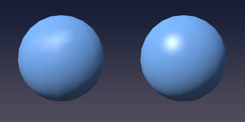
The diffuse part looks almost the same, because it changes slowly over the surface.
The specular highlight is the giveaway: it is a small, sharp peak, and with only a few vertices the Gouraud version either misses it or smears it into a star-shaped blob along the triangle edges, which also swims around when the object rotates.
Per-pixel lighting gets a round highlight no matter how coarse the mesh is.
Why did Gouraud exist at all?
A model has far fewer vertices than the pixels it covers, so it is much cheaper, and for decades that mattered (the fixed-function OpenGL lighting before shaders was Gouraud).
Today per-pixel lighting is the default, and the vertex shader is mostly used to prepare data for it.
13.8 Vertex animation: a waving flag
The vertex shader can do more than multiply by matrices: it can move every vertex to wherever we like, every frame, at almost no cost.
That is how games animate water, grass in the wind, cloth and much more.
There is one catch: the vertex shader can only move vertices that exist.
A flag made of two triangles can only tilt, not wave.
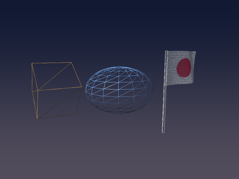
So we need a finely subdivided plane, made by createGrid(32, 20, 1.4f, 0.9f): 32 × 20 small quads, 1.4 × 0.9 units, in the XY plane with its left edge at (where the pole will be).
Here is the whole scene as a wireframe (glPolygonMode(GL_FRONT_AND_BACK, GL_LINE)), so you can see what the vertex shader has to work with:
The wave
I push each vertex along with a sine wave that travels along the flag, and make the amplitude grow from 0 at the pole to at the free edge (width ):
is how many radians the wave advances per unit along , tilts the wave fronts a little so they are not perfectly vertical, and is the speed in radians per second.
The normal
Moving vertices changes the surface, so the old normal is wrong.
Fortunately we know the surface exactly: it is .
Its two tangents are the partial derivatives, and (where means ), and their cross product is the normal:
With the product rule (the amplitude also depends on ):
#version 450 core

layout(location = 0) in vec3 aPosition;
layout(location = 1) in vec3 aNormal;
layout(location = 2) in vec2 aUv;

out vec3 vWorldPos;
out vec3 vNormal;
out vec2 vUv;

uniform mat4 uModel;
uniform mat4 uView;
uniform mat4 uProj;
uniform mat3 uNormalMatrix;
uniform float uTime;

const float AMPLITUDE = 0.15; // wave height (at the free edge)
const float WAVE_K = 5.0;     // wave number (radians per unit along x)
const float WAVE_Y = 1.5;     // wave number along y, for diagonal waves
const float SPEED = 4.0;      // angular speed (radians per second)
const float WIDTH = 1.4;      // flag width (same as the grid in C)

void main() {
  vec3 p = aPosition;

  // still at the pole (x = 0), moving more towards the free edge
  float a = AMPLITUDE * p.x / WIDTH;
  float phase = WAVE_K * p.x + WAVE_Y * p.y - SPEED * uTime;
  p.z = a * sin(phase);

  // normal of the surface z = h(x, y) from the partial derivatives: (-dh/dx, -dh/dy, 1)
  float dhdx = AMPLITUDE / WIDTH * sin(phase) + a * WAVE_K * cos(phase);
  float dhdy = a * WAVE_Y * cos(phase);
  vec3 normal = normalize(vec3(-dhdx, -dhdy, 1.0));

  vec4 worldPos = uModel * vec4(p, 1.0);
  vWorldPos = worldPos.xyz;
  vNormal = uNormalMatrix * normal;
  vUv = aUv;
  gl_Position = uProj * (uView * worldPos);
}
aNormal is not used at all here (the compiler drops unused inputs), and the fragment shader is the same frag_phong.glsl with uPattern = 2.
The flag is a single sheet seen from both sides, so I turn culling off while drawing it (that is why gl_FrontFacing was needed), and turn the flag a little around the pole so the waves are visible:
    // flag: waved in the vertex shader (both sides are visible, so no culling)
    GLuint flagProgram = gPrograms[PROGRAM_FLAG].id;
    setCommonUniforms(flagProgram, view, proj, eye, time);
    glDisable(GL_CULL_FACE);
    Vector3 flagColor = { { 0.95f, 0.95f, 0.92f } };
    Matrix4 flagModel = mat4Multiply(mat4Translate(1.2f, 0.2f, 0.0f), mat4RotateY(0.6f));
    drawLit(flagProgram, &flag, flagModel, flagColor, 2);
    glEnable(GL_CULL_FACE);
Notice that the animation costs the CPU nothing: the mesh in the buffer never changes, we only send one float, uTime.
13.9 gl_VertexID: a fullscreen triangle without buffers
The last trick of this chapter is the background.
Since chapter 5 we have drawn the playground with a quad made of 4 vertices in a buffer.
There is a cheaper way that you will find in almost every engine: one big triangle that covers the whole screen, with no vertex buffer at all.
gl_VertexID is a built-in int input of the vertex shader: the index of the vertex being processed (0, 1, 2, … for glDrawArrays).
From it we can compute the corners ourselves:
#version 450 core

out vec2 vUv;

// a big triangle that covers the whole screen, without any vertex buffer
// gl_VertexID = 0, 1, 2 -> (-1, -1), (3, -1), (-1, 3)
void main() {
  vec2 uv = vec2((gl_VertexID << 1) & 2, gl_VertexID & 2);
  vUv = uv;
  gl_Position = vec4(uv * 2.0 - 1.0, 0.0, 1.0);
}
<< shifts the bits to the left and & keeps only the bits that are set in both numbers (integer operators, as in C):
gl_VertexID |
(id << 1) & 2 |
id & 2 |
uv |
gl_Position.xy |
|---|---|---|---|---|
| 0 | 0 & 2 = 0 | 0 | (0, 0) | (−1, −1) |
| 1 | 2 & 2 = 2 | 0 | (2, 0) | (3, −1) |
| 2 | 4 & 2 = 0 | 2 | (0, 2) | (−1, 3) |
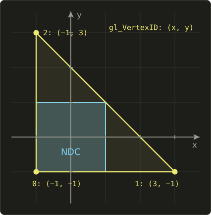
The parts outside the screen are clipped away for free, and inside the screen vUv runs from 0 to 1, just like the quad's UVs.
Why bother?
A quad is two triangles sharing a diagonal, and GPUs shade pixels in small 2×2 blocks, so the pixels along that diagonal are shaded twice; one triangle avoids that and needs no buffer.
For a sky it hardly matters, but post-processing passes run a fullscreen shader many times per frame, and there it adds up.
The fragment shader is a simple vertical gradient using gl_FragCoord from chapter 5:
#version 450 core

in vec2 vUv;
out vec4 out_color;

uniform vec2 uResolution;

void main() {
  float t = gl_FragCoord.y / uResolution.y; // 0 (bottom) to 1 (top)
  vec3 horizon = vec3(0.32, 0.30, 0.36);
  vec3 zenith = vec3(0.07, 0.10, 0.20);
  vec3 color = mix(horizon, zenith, smoothstep(0.0, 1.0, t));
  out_color = vec4(color, 1.0);
}
In the core profile a draw call needs some VAO bound, even if it has no attributes, so we make an empty one once and draw with glDrawArrays.
I draw the sky first with the depth test turned off, so it never hides anything and never writes a depth:
  // an empty VAO to draw without vertex buffers (the core profile requires a VAO)
  GLuint emptyVAO;
  glGenVertexArrays(1, &emptyVAO);
    // background: fullscreen triangle without vertex buffers (no depth test)
    glDisable(GL_DEPTH_TEST);
    GLuint sky = gPrograms[PROGRAM_SKY].id;
    glUseProgram(sky);
    glUniform2f(glGetUniformLocation(sky, "uResolution"), (float)gWidth, (float)gHeight);
    glBindVertexArray(emptyVAO);
    glDrawArrays(GL_TRIANGLES, 0, 3);
    glEnable(GL_DEPTH_TEST);
(Engines often draw the sky last instead, at the far plane with GL_LEQUAL, so that the depth test skips all the pixels already covered by objects.)
13.10 Many programs and hot reload
We now have four shader programs: sky, Phong, Gouraud and flag.
To keep the R hot reload from chapter 5 working for all of them, the C code keeps them in a table and rebuilds every one:
// list of shader programs (R reloads all of them)
typedef struct {
  const char *vertexPath;
  const char *fragmentPath;
  GLuint id;
} Program;

enum { PROGRAM_SKY, PROGRAM_PHONG, PROGRAM_GOURAUD, PROGRAM_FLAG, PROGRAM_COUNT };

static Program gPrograms[PROGRAM_COUNT] = {
  { "shader/vertex_fullscreen.glsl", "shader/frag_sky.glsl", 0 },
  { "shader/vertex_mesh.glsl", "shader/frag_phong.glsl", 0 },
  { "shader/vertex_gouraud.glsl", "shader/frag_gouraud.glsl", 0 },
  { "shader/vertex_flag.glsl", "shader/frag_phong.glsl", 0 },
};

// rebuild all programs (a failed one keeps its old version), returns the number of failures
int loadPrograms(void) {
  int failed = 0;
  for (int i = 0; i < PROGRAM_COUNT; i++) {
    GLuint program = buildProgram(gPrograms[i].vertexPath, gPrograms[i].fragmentPath);
    if (program) {
      if (gPrograms[i].id) glDeleteProgram(gPrograms[i].id);
      gPrograms[i].id = program;
    } else {
      failed++;
    }
  }
  return failed;
}
buildProgram is unchanged from chapter 5, including the macOS #version patch, and everything in this chapter works on OpenGL 4.1, so Mac users get the full chapter.
The rest of main.c (creating the meshes, the G key, the drawing order) is in the diff at the end.
13.11 New GLSL in this chapter
| Feature | What it does |
|---|---|
gl_Position |
Vertex shader output: the position in clip space, divided by its w by the GPU |
mat4 * vec4, mat4 * mat4 |
Real matrix products (column vectors, applied right to left) |
uniform mat4, uniform mat3 |
Matrices from C, set with glUniformMatrix4fv / glUniformMatrix3fv |
mat3(m4) |
The upper-left 3×3 of a mat4 (drops translation) |
inverse(m), transpose(m) |
Matrix inverse and transpose (expensive per vertex: prefer the CPU) |
gl_FrontFacing |
Fragment shader bool: is this triangle facing the camera? |
gl_VertexID |
Vertex shader int: index of the current vertex |
<<, & |
Integer bit shift and bitwise AND |
uniform int |
Integer uniform, set with glUniform1i |
13.12 How this is used in real games and engines
- Model-view-projection is the heart of every 3D renderer. Engines usually combine the matrices per object on the CPU and send
MVP, plus the model matrix and the normal matrix for lighting, often packed into a uniform buffer. - Skeletal animation (skinning): each vertex stores the indices of up to 4 bones and 4 weights, and the vertex shader blends the bones' matrices, . Every animated character you have seen in a game works this way.
- Wind and water: grass, leaves and flags sway with sine waves in the vertex shader, usually weighted by a value painted into the vertex colours (so the roots stay still, like our pole edge). Ocean surfaces add several moving waves (Gerstner waves are a popular choice).
- Instancing: drawing thousands of trees or rocks in one call with
glDrawElementsInstanced, where the vertex shader readsgl_InstanceIDto pick each copy's transform. - Billboards and particles are turned to face the camera in the vertex shader.
- Fullscreen triangles run every post-processing pass: bloom, tone mapping, colour grading, anti-aliasing.
- Gouraud shading is still used where every cycle counts, and as a deliberate retro look (games imitating the PlayStation 1 era).
13.13 Summary
- The vertex shader runs once per vertex and must write
gl_Positionin clip space; the GPU then divides bywand applies the viewport. gl_Position = P * V * M * vec4(pos, 1.0): model, view and projection matrices built in C (matrix.h, column-major like GLSL) and sent withglUniformMatrix4fv(..., GL_FALSE, ...).- Bracket the product as
P * (V * (M * v)), or better, combine the matrices on the CPU. - The depth buffer (
GL_DEPTH_TEST, cleared every frame) sorts out what is in front; back-face culling throws away triangles that face away, using the counter-clockwise winding. - Normals transform with the inverse transpose of the model matrix, which matters as soon as the scale is not uniform; compute it once per object on the CPU.
- Gouraud shading lights per vertex and interpolates colours (cheap, poor highlights); Phong shading interpolates normals and lights per pixel.
- Vertex shaders can animate geometry (our flag), but only vertices that exist; the normal has to be recomputed from the derivatives of the displacement.
gl_VertexIDlets you draw a fullscreen triangle with no vertex buffer, as long as an empty VAO is bound.
13.14 Challenges
- ★ A model matrix scales by . Transform the normal of a surface with tangent once with the model matrix and once with the normal matrix, and check which result is perpendicular to the transformed tangent (you should get a dot product of 3 for one and 0 for the other).
- ★ In the worked example of 13.2, move the cube corner to instead and compute its NDC and its pixel by hand (it should land about 85 pixels from the left edge).
- ★★ Add
glfwWindowHint(GLFW_SAMPLES, 4);before creating the window andglEnable(GL_MULTISAMPLE);after loading GLAD. The jagged edges of the cube and the pole should become smooth (multisample anti-aliasing). - ★★ Let the mouse orbit the camera: compute an angle from
mouseX / windowWand put the eye at . Moving the mouse left and right should circle around the scene, and the lighting should stay attached to the objects, not to the camera. - ★★ Give the flag a second, smaller wave with a different
WAVE_KandSPEED, and add its derivatives todhdxanddhdy. Check your normals by temporarily outputtingn * 0.5 + 0.5as the colour: it should change smoothly, with no seams. - ★★ Change the sphere to
createSphere(64, 48)and press G. The Gouraud and Phong versions should now look almost the same, which is why high-polygon models once hid Gouraud's weaknesses. - ★★★ Draw a 10 × 10 grid of cubes with a single
glDrawElementsInstancedcall. In the vertex shader, usegl_InstanceIDto compute an offset (vec3(id % 10, 0, id / 10)scaled and centred) and add it to the world position. You should see 100 cubes from one draw call.
ファイル: /dev/null | b/include/matrix.h
| 前 | 新 | ||
|---|---|---|---|
| @@ -0,0 +1,149 @@ | |||
| 1 | #pragma once | ||
| 2 | |||
| 3 | // 小さな行列ライブラリ(線型代数シリーズと同じ約束事) | ||
| 4 | // ・列優先(column-major):m[列 * 4 + 行] | ||
| 5 | // ・右手座標系、カメラは-Z方向を向く | ||
| 6 | // ・ベクトルは列ベクトル:v' = M * v | ||
| 7 | |||
| 8 | #include <math.h> | ||
| 9 | #include <vector.h> | ||
| 10 | |||
| 11 | typedef struct { | ||
| 12 | float m[16]; | ||
| 13 | } Matrix4; | ||
| 14 | |||
| 15 | typedef struct { | ||
| 16 | float m[9]; | ||
| 17 | } Matrix3; | ||
| 18 | |||
| 19 | // ベクトルの補助関数 | ||
| 20 | static inline Vector3 vec3Sub(Vector3 a, Vector3 b) { | ||
| 21 | return (Vector3){ { a.x - b.x, a.y - b.y, a.z - b.z } }; | ||
| 22 | } | ||
| 23 | |||
| 24 | static inline float vec3Dot(Vector3 a, Vector3 b) { | ||
| 25 | return a.x * b.x + a.y * b.y + a.z * b.z; | ||
| 26 | } | ||
| 27 | |||
| 28 | static inline Vector3 vec3Cross(Vector3 a, Vector3 b) { | ||
| 29 | return (Vector3){ { a.y * b.z - a.z * b.y, a.z * b.x - a.x * b.z, a.x * b.y - a.y * b.x } }; | ||
| 30 | } | ||
| 31 | |||
| 32 | static inline Vector3 vec3Normalize(Vector3 v) { | ||
| 33 | float len = sqrtf(vec3Dot(v, v)); | ||
| 34 | if (len == 0.0f) return v; | ||
| 35 | return (Vector3){ { v.x / len, v.y / len, v.z / len } }; | ||
| 36 | } | ||
| 37 | |||
| 38 | // 行row・列colの要素(0始まり) | ||
| 39 | static inline float *mat4At(Matrix4 *a, int row, int col) { | ||
| 40 | return &a->m[col * 4 + row]; | ||
| 41 | } | ||
| 42 | |||
| 43 | // 単位行列 | ||
| 44 | static inline Matrix4 mat4Identity(void) { | ||
| 45 | Matrix4 r = { { 0 } }; | ||
| 46 | r.m[0] = r.m[5] = r.m[10] = r.m[15] = 1.0f; | ||
| 47 | return r; | ||
| 48 | } | ||
| 49 | |||
| 50 | // 行列の積 r = a * b(bを先に適用する) | ||
| 51 | static inline Matrix4 mat4Multiply(Matrix4 a, Matrix4 b) { | ||
| 52 | Matrix4 r; | ||
| 53 | for (int col = 0; col < 4; col++) { | ||
| 54 | for (int row = 0; row < 4; row++) { | ||
| 55 | float sum = 0.0f; | ||
| 56 | for (int k = 0; k < 4; k++) sum += a.m[k * 4 + row] * b.m[col * 4 + k]; | ||
| 57 | r.m[col * 4 + row] = sum; | ||
| 58 | } | ||
| 59 | } | ||
| 60 | return r; | ||
| 61 | } | ||
| 62 | |||
| 63 | // 平行移動 | ||
| 64 | static inline Matrix4 mat4Translate(float x, float y, float z) { | ||
| 65 | Matrix4 r = mat4Identity(); | ||
| 66 | r.m[12] = x; // 4列目 | ||
| 67 | r.m[13] = y; | ||
| 68 | r.m[14] = z; | ||
| 69 | return r; | ||
| 70 | } | ||
| 71 | |||
| 72 | // 拡大縮小 | ||
| 73 | static inline Matrix4 mat4Scale(float x, float y, float z) { | ||
| 74 | Matrix4 r = mat4Identity(); | ||
| 75 | r.m[0] = x; | ||
| 76 | r.m[5] = y; | ||
| 77 | r.m[10] = z; | ||
| 78 | return r; | ||
| 79 | } | ||
| 80 | |||
| 81 | // X軸周りの回転(ラジアン、右手の法則で反時計回り) | ||
| 82 | static inline Matrix4 mat4RotateX(float angle) { | ||
| 83 | float c = cosf(angle), s = sinf(angle); | ||
| 84 | Matrix4 r = mat4Identity(); | ||
| 85 | *mat4At(&r, 1, 1) = c; *mat4At(&r, 1, 2) = -s; | ||
| 86 | *mat4At(&r, 2, 1) = s; *mat4At(&r, 2, 2) = c; | ||
| 87 | return r; | ||
| 88 | } | ||
| 89 | |||
| 90 | // Y軸周りの回転 | ||
| 91 | static inline Matrix4 mat4RotateY(float angle) { | ||
| 92 | float c = cosf(angle), s = sinf(angle); | ||
| 93 | Matrix4 r = mat4Identity(); | ||
| 94 | *mat4At(&r, 0, 0) = c; *mat4At(&r, 0, 2) = s; | ||
| 95 | *mat4At(&r, 2, 0) = -s; *mat4At(&r, 2, 2) = c; | ||
| 96 | return r; | ||
| 97 | } | ||
| 98 | |||
| 99 | // ビュー行列:カメラがeyeからtargetを見る | ||
| 100 | static inline Matrix4 mat4LookAt(Vector3 eye, Vector3 target, Vector3 up) { | ||
| 101 | Vector3 f = vec3Normalize(vec3Sub(target, eye)); // 前 | ||
| 102 | Vector3 r = vec3Normalize(vec3Cross(f, up)); // 右 | ||
| 103 | Vector3 u = vec3Cross(r, f); // 上 | ||
| 104 | |||
| 105 | Matrix4 m = mat4Identity(); | ||
| 106 | *mat4At(&m, 0, 0) = r.x; *mat4At(&m, 0, 1) = r.y; *mat4At(&m, 0, 2) = r.z; | ||
| 107 | *mat4At(&m, 1, 0) = u.x; *mat4At(&m, 1, 1) = u.y; *mat4At(&m, 1, 2) = u.z; | ||
| 108 | *mat4At(&m, 2, 0) = -f.x; *mat4At(&m, 2, 1) = -f.y; *mat4At(&m, 2, 2) = -f.z; | ||
| 109 | *mat4At(&m, 0, 3) = -vec3Dot(r, eye); | ||
| 110 | *mat4At(&m, 1, 3) = -vec3Dot(u, eye); | ||
| 111 | *mat4At(&m, 2, 3) = vec3Dot(f, eye); | ||
| 112 | return m; | ||
| 113 | } | ||
| 114 | |||
| 115 | // 透視投影(OpenGL:NDCのzは-1〜1)、fovYは縦の視野角(ラジアン) | ||
| 116 | static inline Matrix4 mat4Perspective(float fovY, float aspect, float n, float f) { | ||
| 117 | float t = 1.0f / tanf(fovY * 0.5f); | ||
| 118 | Matrix4 m = { { 0 } }; | ||
| 119 | *mat4At(&m, 0, 0) = t / aspect; | ||
| 120 | *mat4At(&m, 1, 1) = t; | ||
| 121 | *mat4At(&m, 2, 2) = -(f + n) / (f - n); | ||
| 122 | *mat4At(&m, 2, 3) = -(2.0f * f * n) / (f - n); | ||
| 123 | *mat4At(&m, 3, 2) = -1.0f; | ||
| 124 | return m; | ||
| 125 | } | ||
| 126 | |||
| 127 | // 法線行列:モデル行列の左上3×3の逆行列の転置 | ||
| 128 | // 逆行列の転置 = 余因子行列 / 行列式 なので、余因子を直接計算する | ||
| 129 | static inline Matrix3 mat3NormalMatrix(Matrix4 a) { | ||
| 130 | // 左上3×3の要素(行, 列) | ||
| 131 | float m00 = a.m[0], m10 = a.m[1], m20 = a.m[2]; | ||
| 132 | float m01 = a.m[4], m11 = a.m[5], m21 = a.m[6]; | ||
| 133 | float m02 = a.m[8], m12 = a.m[9], m22 = a.m[10]; | ||
| 134 | |||
| 135 | // 余因子 | ||
| 136 | float c00 = m11 * m22 - m12 * m21, c01 = m12 * m20 - m10 * m22, c02 = m10 * m21 - m11 * m20; | ||
| 137 | float c10 = m02 * m21 - m01 * m22, c11 = m00 * m22 - m02 * m20, c12 = m01 * m20 - m00 * m21; | ||
| 138 | float c20 = m01 * m12 - m02 * m11, c21 = m02 * m10 - m00 * m12, c22 = m00 * m11 - m01 * m10; | ||
| 139 | |||
| 140 | float det = m00 * c00 + m01 * c01 + m02 * c02; | ||
| 141 | float inv = det != 0.0f ? 1.0f / det : 0.0f; | ||
| 142 | |||
| 143 | // 結果の(行i, 列j) = c_ij / det、列優先で格納 | ||
| 144 | Matrix3 r; | ||
| 145 | r.m[0] = c00 * inv; r.m[1] = c10 * inv; r.m[2] = c20 * inv; | ||
| 146 | r.m[3] = c01 * inv; r.m[4] = c11 * inv; r.m[5] = c21 * inv; | ||
| 147 | r.m[6] = c02 * inv; r.m[7] = c12 * inv; r.m[8] = c22 * inv; | ||
| 148 | return r; | ||
| 149 | } | ||
ファイル: a/main.c | b/main.c
| 前 | 新 | ||
|---|---|---|---|
| @@ -11,6 +11,7 @@ | |||
| 11 | #include <stdlib.h> | 11 | #include <stdlib.h> |
| 12 | #include <string.h> | 12 | #include <string.h> |
| 13 | #include <vector.h> | 13 | #include <vector.h> |
| 14 | #include <matrix.h> | ||
| 14 | #include <math.h> | 15 | #include <math.h> |
| 15 | 16 | ||
| 16 | // ファイルパスを構築(プラットフォームに応じて) | 17 | // ファイルパスを構築(プラットフォームに応じて) |
| @@ -176,6 +177,220 @@ GLuint buildProgram(const char *vertexPath, const char *fragmentPath) { | |||
| 176 | return program; | 177 | return program; |
| 177 | } | 178 | } |
| 178 | 179 | ||
| 180 | #define PI 3.14159265358979f | ||
| 181 | |||
| 182 | // メッシュ(頂点配列オブジェクトとインデックスの数) | ||
| 183 | typedef struct { | ||
| 184 | GLuint vao, vbo, ebo; | ||
| 185 | GLsizei indexCount; | ||
| 186 | } Mesh; | ||
| 187 | |||
| 188 | // 頂点の形式:位置(3)、法線(3)、UV(2)=8個のfloat | ||
| 189 | #define VERTEX_FLOATS 8 | ||
| 190 | |||
| 191 | // 頂点とインデックスの配列からメッシュを作る | ||
| 192 | Mesh createMesh(const float *vertices, int vertexCount, const GLuint *indices, int indexCount) { | ||
| 193 | Mesh mesh; | ||
| 194 | mesh.indexCount = indexCount; | ||
| 195 | glGenVertexArrays(1, &mesh.vao); | ||
| 196 | glGenBuffers(1, &mesh.vbo); | ||
| 197 | glGenBuffers(1, &mesh.ebo); | ||
| 198 | |||
| 199 | glBindVertexArray(mesh.vao); | ||
| 200 | glBindBuffer(GL_ARRAY_BUFFER, mesh.vbo); | ||
| 201 | glBufferData(GL_ARRAY_BUFFER, vertexCount * VERTEX_FLOATS * sizeof(float), vertices, GL_STATIC_DRAW); | ||
| 202 | glBindBuffer(GL_ELEMENT_ARRAY_BUFFER, mesh.ebo); | ||
| 203 | glBufferData(GL_ELEMENT_ARRAY_BUFFER, indexCount * sizeof(GLuint), indices, GL_STATIC_DRAW); | ||
| 204 | |||
| 205 | // 頂点属性:位置(location 0)、法線(location 1)、UV(location 2) | ||
| 206 | GLsizei stride = VERTEX_FLOATS * sizeof(float); | ||
| 207 | glVertexAttribPointer(0, 3, GL_FLOAT, GL_FALSE, stride, (void *)0); | ||
| 208 | glEnableVertexAttribArray(0); | ||
| 209 | glVertexAttribPointer(1, 3, GL_FLOAT, GL_FALSE, stride, (void *)(3 * sizeof(float))); | ||
| 210 | glEnableVertexAttribArray(1); | ||
| 211 | glVertexAttribPointer(2, 2, GL_FLOAT, GL_FALSE, stride, (void *)(6 * sizeof(float))); | ||
| 212 | glEnableVertexAttribArray(2); | ||
| 213 | |||
| 214 | glBindVertexArray(0); | ||
| 215 | return mesh; | ||
| 216 | } | ||
| 217 | |||
| 218 | void drawMesh(const Mesh *mesh) { | ||
| 219 | glBindVertexArray(mesh->vao); | ||
| 220 | glDrawElements(GL_TRIANGLES, mesh->indexCount, GL_UNSIGNED_INT, 0); | ||
| 221 | } | ||
| 222 | |||
| 223 | void destroyMesh(Mesh *mesh) { | ||
| 224 | glDeleteVertexArrays(1, &mesh->vao); | ||
| 225 | glDeleteBuffers(1, &mesh->vbo); | ||
| 226 | glDeleteBuffers(1, &mesh->ebo); | ||
| 227 | } | ||
| 228 | |||
| 229 | // 立方体(一辺1、中心が原点):各面に4頂点(面ごとに法線が違う為) | ||
| 230 | Mesh createCube(void) { | ||
| 231 | // 各面:法線n、右方向u、上方向v(u × v = n なので外から見て反時計回り) | ||
| 232 | const float faces[6][9] = { | ||
| 233 | { 1, 0, 0, 0, 0, -1, 0, 1, 0 }, // +X | ||
| 234 | { -1, 0, 0, 0, 0, 1, 0, 1, 0 }, // -X | ||
| 235 | { 0, 1, 0, 1, 0, 0, 0, 0, -1 }, // +Y | ||
| 236 | { 0, -1, 0, 1, 0, 0, 0, 0, 1 }, // -Y | ||
| 237 | { 0, 0, 1, 1, 0, 0, 0, 1, 0 }, // +Z | ||
| 238 | { 0, 0, -1, -1, 0, 0, 0, 1, 0 }, // -Z | ||
| 239 | }; | ||
| 240 | const float corners[4][2] = { { -1, -1 }, { 1, -1 }, { 1, 1 }, { -1, 1 } }; | ||
| 241 | |||
| 242 | float vertices[24 * VERTEX_FLOATS]; | ||
| 243 | GLuint indices[36]; | ||
| 244 | for (int f = 0; f < 6; f++) { | ||
| 245 | const float *n = faces[f], *u = faces[f] + 3, *v = faces[f] + 6; | ||
| 246 | for (int c = 0; c < 4; c++) { | ||
| 247 | float s = corners[c][0], t = corners[c][1]; | ||
| 248 | float *out = &vertices[(f * 4 + c) * VERTEX_FLOATS]; | ||
| 249 | for (int k = 0; k < 3; k++) out[k] = 0.5f * (n[k] + s * u[k] + t * v[k]); // 位置 | ||
| 250 | for (int k = 0; k < 3; k++) out[3 + k] = n[k]; // 法線 | ||
| 251 | out[6] = 0.5f * (s + 1.0f); // UV | ||
| 252 | out[7] = 0.5f * (t + 1.0f); | ||
| 253 | } | ||
| 254 | GLuint base = f * 4; | ||
| 255 | GLuint quad[6] = { base, base + 1, base + 2, base + 2, base + 3, base }; | ||
| 256 | memcpy(&indices[f * 6], quad, sizeof(quad)); | ||
| 257 | } | ||
| 258 | return createMesh(vertices, 24, indices, 36); | ||
| 259 | } | ||
| 260 | |||
| 261 | // UV球(半径1):slices=経度の分割数、stacks=緯度の分割数 | ||
| 262 | Mesh createSphere(int slices, int stacks) { | ||
| 263 | int vertexCount = (slices + 1) * (stacks + 1); | ||
| 264 | int indexCount = slices * stacks * 6; | ||
| 265 | float *vertices = malloc(vertexCount * VERTEX_FLOATS * sizeof(float)); | ||
| 266 | GLuint *indices = malloc(indexCount * sizeof(GLuint)); | ||
| 267 | |||
| 268 | float *out = vertices; | ||
| 269 | for (int i = 0; i <= stacks; i++) { | ||
| 270 | float phi = PI * (float)i / (float)stacks; // 0(北極)〜π(南極) | ||
| 271 | for (int j = 0; j <= slices; j++) { | ||
| 272 | float theta = 2.0f * PI * (float)j / (float)slices; | ||
| 273 | float x = sinf(phi) * sinf(theta); | ||
| 274 | float y = cosf(phi); | ||
| 275 | float z = sinf(phi) * cosf(theta); | ||
| 276 | // 単位球なので、位置と法線は同じ | ||
| 277 | out[0] = x; out[1] = y; out[2] = z; | ||
| 278 | out[3] = x; out[4] = y; out[5] = z; | ||
| 279 | out[6] = (float)j / (float)slices; | ||
| 280 | out[7] = 1.0f - (float)i / (float)stacks; | ||
| 281 | out += VERTEX_FLOATS; | ||
| 282 | } | ||
| 283 | } | ||
| 284 | |||
| 285 | GLuint *idx = indices; | ||
| 286 | for (int i = 0; i < stacks; i++) { | ||
| 287 | for (int j = 0; j < slices; j++) { | ||
| 288 | GLuint a = i * (slices + 1) + j; // 左上 | ||
| 289 | GLuint b = a + slices + 1; // 左下 | ||
| 290 | *idx++ = a; *idx++ = b; *idx++ = a + 1; | ||
| 291 | *idx++ = a + 1; *idx++ = b; *idx++ = b + 1; | ||
| 292 | } | ||
| 293 | } | ||
| 294 | |||
| 295 | Mesh mesh = createMesh(vertices, vertexCount, indices, indexCount); | ||
| 296 | free(vertices); | ||
| 297 | free(indices); | ||
| 298 | return mesh; | ||
| 299 | } | ||
| 300 | |||
| 301 | // XY平面上の格子(幅w、高さh、左下が原点):nx × ny個の四角形 | ||
| 302 | Mesh createGrid(int nx, int ny, float w, float h) { | ||
| 303 | int vertexCount = (nx + 1) * (ny + 1); | ||
| 304 | int indexCount = nx * ny * 6; | ||
| 305 | float *vertices = malloc(vertexCount * VERTEX_FLOATS * sizeof(float)); | ||
| 306 | GLuint *indices = malloc(indexCount * sizeof(GLuint)); | ||
| 307 | |||
| 308 | float *out = vertices; | ||
| 309 | for (int j = 0; j <= ny; j++) { | ||
| 310 | for (int i = 0; i <= nx; i++) { | ||
| 311 | float u = (float)i / (float)nx, v = (float)j / (float)ny; | ||
| 312 | out[0] = u * w; out[1] = v * h; out[2] = 0.0f; | ||
| 313 | out[3] = 0.0f; out[4] = 0.0f; out[5] = 1.0f; | ||
| 314 | out[6] = u; out[7] = v; | ||
| 315 | out += VERTEX_FLOATS; | ||
| 316 | } | ||
| 317 | } | ||
| 318 | |||
| 319 | GLuint *idx = indices; | ||
| 320 | for (int j = 0; j < ny; j++) { | ||
| 321 | for (int i = 0; i < nx; i++) { | ||
| 322 | GLuint a = j * (nx + 1) + i; // 左下 | ||
| 323 | GLuint b = a + nx + 1; // 左上 | ||
| 324 | *idx++ = a; *idx++ = a + 1; *idx++ = b + 1; | ||
| 325 | *idx++ = b + 1; *idx++ = b; *idx++ = a; | ||
| 326 | } | ||
| 327 | } | ||
| 328 | |||
| 329 | Mesh mesh = createMesh(vertices, vertexCount, indices, indexCount); | ||
| 330 | free(vertices); | ||
| 331 | free(indices); | ||
| 332 | return mesh; | ||
| 333 | } | ||
| 334 | |||
| 335 | // 行列のユニフォームを設定(列優先のままなのでtransposeはGL_FALSE) | ||
| 336 | void setMat4(GLuint program, const char *name, Matrix4 m) { | ||
| 337 | glUniformMatrix4fv(glGetUniformLocation(program, name), 1, GL_FALSE, m.m); | ||
| 338 | } | ||
| 339 | |||
| 340 | void setMat3(GLuint program, const char *name, Matrix3 m) { | ||
| 341 | glUniformMatrix3fv(glGetUniformLocation(program, name), 1, GL_FALSE, m.m); | ||
| 342 | } | ||
| 343 | |||
| 344 | // シェーダープログラムの一覧(Rキーで全部再読み込み) | ||
| 345 | typedef struct { | ||
| 346 | const char *vertexPath; | ||
| 347 | const char *fragmentPath; | ||
| 348 | GLuint id; | ||
| 349 | } Program; | ||
| 350 | |||
| 351 | enum { PROGRAM_SKY, PROGRAM_PHONG, PROGRAM_GOURAUD, PROGRAM_FLAG, PROGRAM_COUNT }; | ||
| 352 | |||
| 353 | static Program gPrograms[PROGRAM_COUNT] = { | ||
| 354 | { "shader/vertex_fullscreen.glsl", "shader/frag_sky.glsl", 0 }, | ||
| 355 | { "shader/vertex_mesh.glsl", "shader/frag_phong.glsl", 0 }, | ||
| 356 | { "shader/vertex_gouraud.glsl", "shader/frag_gouraud.glsl", 0 }, | ||
| 357 | { "shader/vertex_flag.glsl", "shader/frag_phong.glsl", 0 }, | ||
| 358 | }; | ||
| 359 | |||
| 360 | // 全てのプログラムを作り直す(失敗した物は前のままにする)、失敗の数を返す | ||
| 361 | int loadPrograms(void) { | ||
| 362 | int failed = 0; | ||
| 363 | for (int i = 0; i < PROGRAM_COUNT; i++) { | ||
| 364 | GLuint program = buildProgram(gPrograms[i].vertexPath, gPrograms[i].fragmentPath); | ||
| 365 | if (program) { | ||
| 366 | if (gPrograms[i].id) glDeleteProgram(gPrograms[i].id); | ||
| 367 | gPrograms[i].id = program; | ||
| 368 | } else { | ||
| 369 | failed++; | ||
| 370 | } | ||
| 371 | } | ||
| 372 | return failed; | ||
| 373 | } | ||
| 374 | |||
| 375 | // 照明付きの物体を描く(モデル行列から法線行列も計算する) | ||
| 376 | void drawLit(GLuint program, const Mesh *mesh, Matrix4 model, Vector3 color, int pattern) { | ||
| 377 | setMat4(program, "uModel", model); | ||
| 378 | setMat3(program, "uNormalMatrix", mat3NormalMatrix(model)); | ||
| 379 | glUniform3f(glGetUniformLocation(program, "uColor"), color.r, color.g, color.b); | ||
| 380 | glUniform1i(glGetUniformLocation(program, "uPattern"), pattern); | ||
| 381 | drawMesh(mesh); | ||
| 382 | } | ||
| 383 | |||
| 384 | // 全てのプログラムで共通のユニフォーム | ||
| 385 | void setCommonUniforms(GLuint program, Matrix4 view, Matrix4 proj, Vector3 eye, float time) { | ||
| 386 | glUseProgram(program); | ||
| 387 | setMat4(program, "uView", view); | ||
| 388 | setMat4(program, "uProj", proj); | ||
| 389 | glUniform3f(glGetUniformLocation(program, "uCameraPos"), eye.x, eye.y, eye.z); | ||
| 390 | glUniform3f(glGetUniformLocation(program, "uLightDir"), -0.5f, 0.8f, 0.6f); // 光の方へ向かう方向 | ||
| 391 | glUniform1f(glGetUniformLocation(program, "uTime"), time); | ||
| 392 | } | ||
| 393 | |||
| 179 | int main(int argc, char **argv) { | 394 | int main(int argc, char **argv) { |
| 180 | (void)argc; | 395 | (void)argc; |
| 181 | (void)argv; | 396 | (void)argv; |
| @@ -202,7 +417,7 @@ int main(int argc, char **argv) { | |||
| 202 | #endif | 417 | #endif |
| 203 | 418 | ||
| 204 | // ウィンドウを作成 | 419 | // ウィンドウを作成 |
| 205 | GLFWwindow *window = glfwCreateWindow(800, 600, "GLSLシェーダープレイグラウンド", NULL, NULL); | 420 | GLFWwindow *window = glfwCreateWindow(800, 600, "GLSLシェーダー:頂点シェーダーと3D", NULL, NULL); |
| 206 | if (!window) { | 421 | if (!window) { |
| 207 | puts("GLFWウィンドウの作成に失敗しました"); | 422 | puts("GLFWウィンドウの作成に失敗しました"); |
| 208 | glfwTerminate(); | 423 | glfwTerminate(); |
| @@ -224,44 +439,31 @@ int main(int argc, char **argv) { | |||
| 224 | glfwSetFramebufferSizeCallback(window, framebuffer_size_callback); | 439 | glfwSetFramebufferSizeCallback(window, framebuffer_size_callback); |
| 225 | 440 | ||
| 226 | // シェーダーを読み込む | 441 | // シェーダーを読み込む |
| 227 | const char *vertexPath = "shader/vertex.glsl"; | 442 | if (loadPrograms() > 0) { |
| 228 | const char *fragmentPath = "shader/playground.glsl"; | ||
| 229 | GLuint shaderProgram = buildProgram(vertexPath, fragmentPath); | ||
| 230 | if (!shaderProgram) { | ||
| 231 | puts("シェーダーの読み込みに失敗しました"); | 443 | puts("シェーダーの読み込みに失敗しました"); |
| 232 | glfwDestroyWindow(window); | 444 | glfwDestroyWindow(window); |
| 233 | glfwTerminate(); | 445 | glfwTerminate(); |
| 234 | return -1; | 446 | return -1; |
| 235 | } | 447 | } |
| 236 | 448 | ||
| 237 | // 頂点データ(フルスクリーンクアッド)を設定 | 449 | // メッシュを作る |
| 238 | float vertices[] = { | 450 | Mesh cube = createCube(); |
| 239 | -1.0f, -1.0f, 0.0f, 0.0f, // 左下(位置、UV) | 451 | Mesh sphere = createSphere(16, 12); |
| 240 | 1.0f, -1.0f, 1.0f, 0.0f, // 右下 | 452 | Mesh flag = createGrid(32, 20, 1.4f, 0.9f); |
| 241 | 1.0f, 1.0f, 1.0f, 1.0f, // 右上 | ||
| 242 | -1.0f, 1.0f, 0.0f, 1.0f // 左上 | ||
| 243 | }; | ||
| 244 | GLuint indices[] = { 0, 1, 2, 2, 3, 0 }; | ||
| 245 | |||
| 246 | GLuint VAO, VBO, EBO; | ||
| 247 | glGenVertexArrays(1, &VAO); | ||
| 248 | glGenBuffers(1, &VBO); | ||
| 249 | glGenBuffers(1, &EBO); | ||
| 250 | 453 | ||
| 251 | glBindVertexArray(VAO); | 454 | // 頂点バッファなしで描く為の空のVAO(コアプロファイルではVAOが必須) |
| 252 | glBindBuffer(GL_ARRAY_BUFFER, VBO); | 455 | GLuint emptyVAO; |
| 253 | glBufferData(GL_ARRAY_BUFFER, sizeof(vertices), vertices, GL_STATIC_DRAW); | 456 | glGenVertexArrays(1, &emptyVAO); |
| 254 | glBindBuffer(GL_ELEMENT_ARRAY_BUFFER, EBO); | ||
| 255 | glBufferData(GL_ELEMENT_ARRAY_BUFFER, sizeof(indices), indices, GL_STATIC_DRAW); | ||
| 256 | 457 | ||
| 257 | // 頂点属性:位置(location 0)、UV(location 1) | 458 | // 深度テストと裏面カリング |
| 258 | glVertexAttribPointer(0, 2, GL_FLOAT, GL_FALSE, 4 * sizeof(float), (void *)0); | 459 | glEnable(GL_DEPTH_TEST); |
| 259 | glEnableVertexAttribArray(0); | 460 | glEnable(GL_CULL_FACE); |
| 260 | size_t offset = 2 * sizeof(float); | 461 | glCullFace(GL_BACK); |
| 261 | glVertexAttribPointer(1, 2, GL_FLOAT, GL_FALSE, 4 * sizeof(float), (void *)offset); | 462 | glFrontFace(GL_CCW); |
| 262 | glEnableVertexAttribArray(1); | ||
| 263 | 463 | ||
| 264 | int reloadWasDown = 0; | 464 | int reloadWasDown = 0; |
| 465 | int gouraudWasDown = 0; | ||
| 466 | int useGouraud = 0; | ||
| 265 | 467 | ||
| 266 | // メインレンダリングループ | 468 | // メインレンダリングループ |
| 267 | while (!glfwWindowShouldClose(window)) { | 469 | while (!glfwWindowShouldClose(window)) { |
| @@ -271,40 +473,72 @@ int main(int argc, char **argv) { | |||
| 271 | // Rキーでシェーダーを再読み込み(失敗したら古いシェーダーのまま) | 473 | // Rキーでシェーダーを再読み込み(失敗したら古いシェーダーのまま) |
| 272 | int reloadDown = glfwGetKey(window, GLFW_KEY_R) == GLFW_PRESS; | 474 | int reloadDown = glfwGetKey(window, GLFW_KEY_R) == GLFW_PRESS; |
| 273 | if (reloadDown && !reloadWasDown) { | 475 | if (reloadDown && !reloadWasDown) { |
| 274 | GLuint newProgram = buildProgram(vertexPath, fragmentPath); | 476 | if (loadPrograms() == 0) puts("シェーダーを再読み込みしました"); |
| 275 | if (newProgram) { | 477 | else puts("再読み込みに失敗しました。前のシェーダーを使い続けます"); |
| 276 | glDeleteProgram(shaderProgram); | ||
| 277 | shaderProgram = newProgram; | ||
| 278 | puts("シェーダーを再読み込みしました"); | ||
| 279 | } else { | ||
| 280 | puts("再読み込みに失敗しました。前のシェーダーを使い続けます"); | ||
| 281 | } | ||
| 282 | } | 478 | } |
| 283 | reloadWasDown = reloadDown; | 479 | reloadWasDown = reloadDown; |
| 284 | 480 | ||
| 285 | // 画面をクリア | 481 | // Gキーで頂点ごとのライティング(グーロー)とピクセルごと(フォン)を切り替える |
| 286 | glClearColor(0.0f, 0.0f, 0.0f, 1.0f); | 482 | int gouraudDown = glfwGetKey(window, GLFW_KEY_G) == GLFW_PRESS; |
| 287 | glClear(GL_COLOR_BUFFER_BIT); | 483 | if (gouraudDown && !gouraudWasDown) { |
| 288 | 484 | useGouraud = !useGouraud; | |
| 289 | // シェーダープログラムを使用 | 485 | puts(useGouraud ? "頂点ごとのライティング(グーロー)" : "ピクセルごとのライティング(フォン)"); |
| 290 | glUseProgram(shaderProgram); | 486 | } |
| 291 | 487 | gouraudWasDown = gouraudDown; | |
| 292 | // マウスの位置(ピクセル、左下が原点になる様にyを反転) | ||
| 293 | double mouseX, mouseY; | ||
| 294 | glfwGetCursorPos(window, &mouseX, &mouseY); | ||
| 295 | int windowW, windowH; | ||
| 296 | glfwGetWindowSize(window, &windowW, &windowH); | ||
| 297 | float scale = windowW > 0 ? (float)gWidth / (float)windowW : 1.0f; | ||
| 298 | 488 | ||
| 299 | // ユニフォームを設定 | 489 | float time = (float)glfwGetTime(); |
| 300 | glUniform1f(glGetUniformLocation(shaderProgram, "uTime"), (float)glfwGetTime()); | ||
| 301 | glUniform2f(glGetUniformLocation(shaderProgram, "uResolution"), (float)gWidth, (float)gHeight); | ||
| 302 | glUniform2f(glGetUniformLocation(shaderProgram, "uMouse"), | ||
| 303 | (float)mouseX * scale, (float)(windowH - mouseY) * scale); | ||
| 304 | 490 | ||
| 305 | // クアッドを描画 | 491 | // 画面と深度バッファをクリア |
| 306 | glBindVertexArray(VAO); | 492 | glClearColor(0.0f, 0.0f, 0.0f, 1.0f); |
| 307 | glDrawElements(GL_TRIANGLES, 6, GL_UNSIGNED_INT, 0); | 493 | glClear(GL_COLOR_BUFFER_BIT | GL_DEPTH_BUFFER_BIT); |
| 494 | |||
| 495 | // 背景:頂点バッファなしのフルスクリーン三角形(深度テストなし) | ||
| 496 | glDisable(GL_DEPTH_TEST); | ||
| 497 | GLuint sky = gPrograms[PROGRAM_SKY].id; | ||
| 498 | glUseProgram(sky); | ||
| 499 | glUniform2f(glGetUniformLocation(sky, "uResolution"), (float)gWidth, (float)gHeight); | ||
| 500 | glBindVertexArray(emptyVAO); | ||
| 501 | glDrawArrays(GL_TRIANGLES, 0, 3); | ||
| 502 | glEnable(GL_DEPTH_TEST); | ||
| 503 | |||
| 504 | // カメラ:ビュー行列と投影行列 | ||
| 505 | Vector3 eye = { { 0.0f, 1.0f, 5.0f } }; | ||
| 506 | Vector3 target = { { 0.0f, 0.1f, 0.0f } }; | ||
| 507 | Vector3 up = { { 0.0f, 1.0f, 0.0f } }; | ||
| 508 | Matrix4 view = mat4LookAt(eye, target, up); | ||
| 509 | float aspect = gHeight > 0 ? (float)gWidth / (float)gHeight : 1.0f; | ||
| 510 | Matrix4 proj = mat4Perspective(50.0f * PI / 180.0f, aspect, 0.1f, 100.0f); | ||
| 511 | |||
| 512 | // 立方体と球(Gキーでシェーダーを切り替え) | ||
| 513 | GLuint lit = useGouraud ? gPrograms[PROGRAM_GOURAUD].id : gPrograms[PROGRAM_PHONG].id; | ||
| 514 | setCommonUniforms(lit, view, proj, eye, time); | ||
| 515 | |||
| 516 | // 立方体:回転してから左へ移動(M = T * R) | ||
| 517 | Matrix4 cubeModel = mat4Multiply(mat4Translate(-1.7f, 0.1f, 0.0f), | ||
| 518 | mat4Multiply(mat4RotateY(time * 0.7f), mat4RotateX(0.6f))); | ||
| 519 | Vector3 cubeColor = { { 0.9f, 0.45f, 0.1f } }; | ||
| 520 | drawLit(lit, &cube, cubeModel, cubeColor, 1); | ||
| 521 | |||
| 522 | // 球:わざと潰してから回転(M = T * R * S)、法線行列が必要になる | ||
| 523 | Matrix4 sphereModel = mat4Multiply(mat4Translate(0.0f, 0.1f, 0.0f), | ||
| 524 | mat4Multiply(mat4RotateY(time * 0.5f), | ||
| 525 | mat4Scale(0.9f, 0.6f, 0.9f))); | ||
| 526 | Vector3 sphereColor = { { 0.2f, 0.45f, 0.9f } }; | ||
| 527 | drawLit(lit, &sphere, sphereModel, sphereColor, 1); | ||
| 528 | |||
| 529 | // 旗竿:細長く伸ばした立方体 | ||
| 530 | Matrix4 poleModel = mat4Multiply(mat4Translate(1.2f, 0.0f, 0.0f), mat4Scale(0.05f, 2.2f, 0.05f)); | ||
| 531 | Vector3 poleColor = { { 0.8f, 0.8f, 0.75f } }; | ||
| 532 | drawLit(lit, &cube, poleModel, poleColor, 0); | ||
| 533 | |||
| 534 | // 旗:頂点シェーダーで波打たせる(両面を描くのでカリングなし) | ||
| 535 | GLuint flagProgram = gPrograms[PROGRAM_FLAG].id; | ||
| 536 | setCommonUniforms(flagProgram, view, proj, eye, time); | ||
| 537 | glDisable(GL_CULL_FACE); | ||
| 538 | Vector3 flagColor = { { 0.95f, 0.95f, 0.92f } }; | ||
| 539 | Matrix4 flagModel = mat4Multiply(mat4Translate(1.2f, 0.2f, 0.0f), mat4RotateY(0.6f)); | ||
| 540 | drawLit(flagProgram, &flag, flagModel, flagColor, 2); | ||
| 541 | glEnable(GL_CULL_FACE); | ||
| 308 | 542 | ||
| 309 | // バッファをスワップし、イベントを処理 | 543 | // バッファをスワップし、イベントを処理 |
| 310 | glfwSwapBuffers(window); | 544 | glfwSwapBuffers(window); |
| @@ -312,10 +546,11 @@ int main(int argc, char **argv) { | |||
| 312 | } | 546 | } |
| 313 | 547 | ||
| 314 | // クリーンアップ | 548 | // クリーンアップ |
| 315 | glDeleteVertexArrays(1, &VAO); | 549 | destroyMesh(&cube); |
| 316 | glDeleteBuffers(1, &VBO); | 550 | destroyMesh(&sphere); |
| 317 | glDeleteBuffers(1, &EBO); | 551 | destroyMesh(&flag); |
| 318 | glDeleteProgram(shaderProgram); | 552 | glDeleteVertexArrays(1, &emptyVAO); |
| 553 | for (int i = 0; i < PROGRAM_COUNT; i++) glDeleteProgram(gPrograms[i].id); | ||
| 319 | glfwDestroyWindow(window); | 554 | glfwDestroyWindow(window); |
| 320 | glfwTerminate(); | 555 | glfwTerminate(); |
| 321 | 556 | ||
ファイル: /dev/null | b/shader/frag_gouraud.glsl
| 前 | 新 | ||
|---|---|---|---|
| @@ -0,0 +1,8 @@ | |||
| 1 | #version 450 core | ||
| 2 | |||
| 3 | in vec3 vColor; // ラスタライザーが三角形の中で補間した色 | ||
| 4 | out vec4 out_color; | ||
| 5 | |||
| 6 | void main() { | ||
| 7 | out_color = vec4(pow(vColor, vec3(1.0 / 2.2)), 1.0); | ||
| 8 | } | ||
ファイル: /dev/null | b/shader/frag_phong.glsl
| 前 | 新 | ||
|---|---|---|---|
| @@ -0,0 +1,43 @@ | |||
| 1 | #version 450 core | ||
| 2 | |||
| 3 | in vec3 vWorldPos; | ||
| 4 | in vec3 vNormal; | ||
| 5 | in vec2 vUv; | ||
| 6 | out vec4 out_color; | ||
| 7 | |||
| 8 | uniform vec3 uColor; // 物体の色(リニア) | ||
| 9 | uniform vec3 uLightDir; // 表面から光の方へ向かう方向(ワールド空間) | ||
| 10 | uniform vec3 uCameraPos; // カメラの位置(ワールド空間) | ||
| 11 | uniform int uPattern; // 0:単色、1:チェッカー、2:日の丸 | ||
| 12 | |||
| 13 | // UVから物体の色を決める | ||
| 14 | vec3 albedo() { | ||
| 15 | if (uPattern == 1) { | ||
| 16 | vec2 cell = floor(vUv * 4.0); | ||
| 17 | float checker = mod(cell.x + cell.y, 2.0); | ||
| 18 | return uColor * mix(0.55, 1.0, checker); | ||
| 19 | } | ||
| 20 | if (uPattern == 2) { | ||
| 21 | vec2 p = (vUv - 0.5) * vec2(1.4 / 0.9, 1.0); // 旗の縦横比 | ||
| 22 | float disc = 1.0 - smoothstep(0.29, 0.31, length(p)); | ||
| 23 | return mix(uColor, vec3(0.75, 0.02, 0.05), disc); | ||
| 24 | } | ||
| 25 | return uColor; | ||
| 26 | } | ||
| 27 | |||
| 28 | void main() { | ||
| 29 | vec3 n = normalize(vNormal); | ||
| 30 | if (!gl_FrontFacing) n = -n; // 裏面(旗の裏側)では法線を反転 | ||
| 31 | vec3 l = normalize(uLightDir); | ||
| 32 | vec3 v = normalize(uCameraPos - vWorldPos); | ||
| 33 | vec3 h = normalize(l + v); // ハーフベクトル(Blinn-Phong) | ||
| 34 | |||
| 35 | float diffuse = max(dot(n, l), 0.0); | ||
| 36 | float specular = diffuse > 0.0 ? pow(max(dot(n, h), 0.0), 64.0) : 0.0; | ||
| 37 | |||
| 38 | // 空と地面の色の半球ライト(アンビエント) | ||
| 39 | vec3 ambient = mix(vec3(0.05, 0.04, 0.03), vec3(0.10, 0.13, 0.20), n.y * 0.5 + 0.5); | ||
| 40 | |||
| 41 | vec3 color = albedo() * (ambient + diffuse) + vec3(0.6) * specular; | ||
| 42 | out_color = vec4(pow(color, vec3(1.0 / 2.2)), 1.0); // ガンマ補正 | ||
| 43 | } | ||
ファイル: /dev/null | b/shader/frag_sky.glsl
| 前 | 新 | ||
|---|---|---|---|
| @@ -0,0 +1,14 @@ | |||
| 1 | #version 450 core | ||
| 2 | |||
| 3 | in vec2 vUv; | ||
| 4 | out vec4 out_color; | ||
| 5 | |||
| 6 | uniform vec2 uResolution; | ||
| 7 | |||
| 8 | void main() { | ||
| 9 | float t = gl_FragCoord.y / uResolution.y; // 0(下)〜1(上) | ||
| 10 | vec3 horizon = vec3(0.32, 0.30, 0.36); | ||
| 11 | vec3 zenith = vec3(0.07, 0.10, 0.20); | ||
| 12 | vec3 color = mix(horizon, zenith, smoothstep(0.0, 1.0, t)); | ||
| 13 | out_color = vec4(color, 1.0); | ||
| 14 | } | ||
ファイル: /dev/null | b/shader/vertex_flag.glsl
| 前 | 新 | ||
|---|---|---|---|
| @@ -0,0 +1,41 @@ | |||
| 1 | #version 450 core | ||
| 2 | |||
| 3 | layout(location = 0) in vec3 aPosition; | ||
| 4 | layout(location = 1) in vec3 aNormal; | ||
| 5 | layout(location = 2) in vec2 aUv; | ||
| 6 | |||
| 7 | out vec3 vWorldPos; | ||
| 8 | out vec3 vNormal; | ||
| 9 | out vec2 vUv; | ||
| 10 | |||
| 11 | uniform mat4 uModel; | ||
| 12 | uniform mat4 uView; | ||
| 13 | uniform mat4 uProj; | ||
| 14 | uniform mat3 uNormalMatrix; | ||
| 15 | uniform float uTime; | ||
| 16 | |||
| 17 | const float AMPLITUDE = 0.15; // 波の高さ(旗の端で) | ||
| 18 | const float WAVE_K = 5.0; // 波数(x方向に1あたり何ラジアン) | ||
| 19 | const float WAVE_Y = 1.5; // 斜めの波にする為のy方向の波数 | ||
| 20 | const float SPEED = 4.0; // 角速度(ラジアン/秒) | ||
| 21 | const float WIDTH = 1.4; // 旗の幅(C側の格子と同じ) | ||
| 22 | |||
| 23 | void main() { | ||
| 24 | vec3 p = aPosition; | ||
| 25 | |||
| 26 | // 竿(x = 0)では動かず、端に行く程大きく揺れる | ||
| 27 | float a = AMPLITUDE * p.x / WIDTH; | ||
| 28 | float phase = WAVE_K * p.x + WAVE_Y * p.y - SPEED * uTime; | ||
| 29 | p.z = a * sin(phase); | ||
| 30 | |||
| 31 | // 法線:曲面 z = h(x, y) の偏微分から (-dh/dx, -dh/dy, 1) | ||
| 32 | float dhdx = AMPLITUDE / WIDTH * sin(phase) + a * WAVE_K * cos(phase); | ||
| 33 | float dhdy = a * WAVE_Y * cos(phase); | ||
| 34 | vec3 normal = normalize(vec3(-dhdx, -dhdy, 1.0)); | ||
| 35 | |||
| 36 | vec4 worldPos = uModel * vec4(p, 1.0); | ||
| 37 | vWorldPos = worldPos.xyz; | ||
| 38 | vNormal = uNormalMatrix * normal; | ||
| 39 | vUv = aUv; | ||
| 40 | gl_Position = uProj * (uView * worldPos); | ||
| 41 | } | ||
ファイル: /dev/null | b/shader/vertex_fullscreen.glsl
| 前 | 新 | ||
|---|---|---|---|
| @@ -0,0 +1,11 @@ | |||
| 1 | #version 450 core | ||
| 2 | |||
| 3 | out vec2 vUv; | ||
| 4 | |||
| 5 | // 頂点バッファなしで画面全体を覆う大きな三角形 | ||
| 6 | // gl_VertexID = 0, 1, 2 → (-1, -1), (3, -1), (-1, 3) | ||
| 7 | void main() { | ||
| 8 | vec2 uv = vec2((gl_VertexID << 1) & 2, gl_VertexID & 2); | ||
| 9 | vUv = uv; | ||
| 10 | gl_Position = vec4(uv * 2.0 - 1.0, 0.0, 1.0); | ||
| 11 | } | ||
ファイル: /dev/null | b/shader/vertex_gouraud.glsl
| 前 | 新 | ||
|---|---|---|---|
| @@ -0,0 +1,30 @@ | |||
| 1 | #version 450 core | ||
| 2 | |||
| 3 | layout(location = 0) in vec3 aPosition; | ||
| 4 | layout(location = 1) in vec3 aNormal; | ||
| 5 | layout(location = 2) in vec2 aUv; | ||
| 6 | |||
| 7 | out vec3 vColor; // 頂点で計算したライティングの結果 | ||
| 8 | |||
| 9 | uniform mat4 uModel; | ||
| 10 | uniform mat4 uView; | ||
| 11 | uniform mat4 uProj; | ||
| 12 | uniform mat3 uNormalMatrix; | ||
| 13 | uniform vec3 uColor; | ||
| 14 | uniform vec3 uLightDir; | ||
| 15 | uniform vec3 uCameraPos; | ||
| 16 | |||
| 17 | void main() { | ||
| 18 | vec4 worldPos = uModel * vec4(aPosition, 1.0); | ||
| 19 | vec3 n = normalize(uNormalMatrix * aNormal); | ||
| 20 | vec3 l = normalize(uLightDir); | ||
| 21 | vec3 v = normalize(uCameraPos - worldPos.xyz); | ||
| 22 | vec3 h = normalize(l + v); | ||
| 23 | |||
| 24 | float diffuse = max(dot(n, l), 0.0); | ||
| 25 | float specular = diffuse > 0.0 ? pow(max(dot(n, h), 0.0), 64.0) : 0.0; | ||
| 26 | vec3 ambient = mix(vec3(0.05, 0.04, 0.03), vec3(0.10, 0.13, 0.20), n.y * 0.5 + 0.5); | ||
| 27 | |||
| 28 | vColor = uColor * (ambient + diffuse) + vec3(0.6) * specular; | ||
| 29 | gl_Position = uProj * (uView * worldPos); | ||
| 30 | } | ||
ファイル: /dev/null | b/shader/vertex_mesh.glsl
| 前 | 新 | ||
|---|---|---|---|
| @@ -0,0 +1,22 @@ | |||
| 1 | #version 450 core | ||
| 2 | |||
| 3 | layout(location = 0) in vec3 aPosition; | ||
| 4 | layout(location = 1) in vec3 aNormal; | ||
| 5 | layout(location = 2) in vec2 aUv; | ||
| 6 | |||
| 7 | out vec3 vWorldPos; // ワールド空間の位置 | ||
| 8 | out vec3 vNormal; // ワールド空間の法線 | ||
| 9 | out vec2 vUv; | ||
| 10 | |||
| 11 | uniform mat4 uModel; // オブジェクト空間 → ワールド空間 | ||
| 12 | uniform mat4 uView; // ワールド空間 → ビュー空間 | ||
| 13 | uniform mat4 uProj; // ビュー空間 → クリップ空間 | ||
| 14 | uniform mat3 uNormalMatrix; // 法線用(モデル行列の逆行列の転置) | ||
| 15 | |||
| 16 | void main() { | ||
| 17 | vec4 worldPos = uModel * vec4(aPosition, 1.0); | ||
| 18 | vWorldPos = worldPos.xyz; | ||
| 19 | vNormal = uNormalMatrix * aNormal; | ||
| 20 | vUv = aUv; | ||
| 21 | gl_Position = uProj * (uView * worldPos); | ||
| 22 | } | ||
コメント(0)
まだコメントはありません。
ログインするとコメント出来ます。