11. Coordinate Spaces and the Camera
Over the last few chapters we built a real toolbox: matrices that scale, rotate and move things (chapters 8 and 9), and inverse matrices that undo them (chapter 10).
In this chapter I'll put that toolbox to work on the most important object in any 3D program: the camera.
We'll follow one vertex on its trip from a model file to a pixel, learn what "changing coordinate spaces" really means, and build the famous lookAt view matrix from scratch.
By the end you'll be able to write a first-person camera and an orbit camera yourself.
11.1 The journey of a vertex
Imagine telling a friend where your coffee mug is.
You could say "10 cm to the left of my keyboard", or "in room 302 on the third floor", or give its GPS coordinates.
It's the same mug every time.
Only the reference frame changed: where you put the origin, and which directions you call the axes.
A 3D program does exactly this, several times for every vertex, every frame.
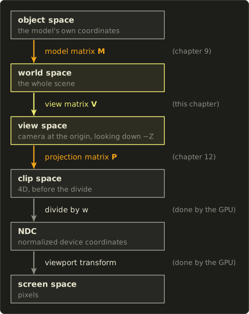
Each reference frame is called a space, and a matrix moves a point from one space to the next:
| Space | Where is the origin? | What it's used for |
|---|---|---|
| Object (local) | the model's pivot, chosen by the artist | vertex data stored in the file |
| World | one fixed point of the scene | placing objects, physics, lights |
| View (camera) | the camera's eye | the camera looks down −Z here |
| Clip | no simple origin (4D homogeneous) | the GPU cuts away what's off-screen |
| NDC | the center of the screen | x and y squeezed into −1 to 1 |
| Screen | a corner of the window | actual pixels |
We write the first three arrows ourselves in the vertex shader.
The GPU does the last two for us.
You already know the model matrix: it's the matrix from chapter 9.
The projection matrix gets its own chapter next.
This chapter is about the view matrix, and about the one idea hiding behind every arrow in that diagram: change of basis.
11.2 Change of basis: the formula
Here is the picture.
The grid below has the usual x and y axes, but someone else uses tilted axes and instead.
Both of you can describe the same point P, you'll just write down different numbers.
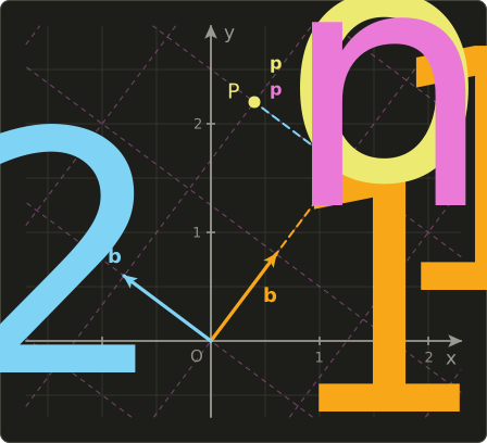
Write the new basis vectors in the old coordinates and put them into a matrix as its columns:
If a point has coordinates measured along the new axes, then its old coordinates are:
To go the other way, undo with its inverse (chapter 10):
And if the new axes are orthonormal (each one has length 1, and they're all perpendicular to each other), the inverse is simply the transpose:
When the new frame also has its own origin (written in old coordinates), we use the 4×4 trick from chapter 9 and put into the fourth column:
11.3 How change of basis works
What does mean?
It means "walk 2 steps along , then 1 step along ".
In old coordinates that walk is .
Remember chapter 6: a matrix times a vector is exactly a linear combination of the matrix's columns.
So , and that's the whole formula.
Going back is a question: "how many steps along is this point?"
For an orthonormal basis, chapter 4 already answered it: the dot product with a unit vector measures how far a vector reaches along that direction.
So the new coordinates are just and .
Doing several dot products at once is a matrix whose rows are and , and that matrix is .
This is why the transpose undoes an orthonormal matrix, the same fact we used for rotations in chapter 10.
A worked 2D example
Take the new axes
First let's check that they're orthonormal:
Good: both have length 1 and they're perpendicular.
(They're just the normal x and y axes rotated by about 53°.)
Now a point has new coordinates .
New to old:
And back again, old to new, with the transpose (rows are and ):
We got back, so the round trip works.
If the new axes were not orthonormal (say one of them had length 2), the transpose would give a wrong answer and you'd need the real inverse from chapter 10.
Here's the sentence I want you to remember from this section:
A matrix whose columns are the axes (and origin) of frame A, written in frame B's coordinates, converts points from A to B, and its inverse converts from B back to A.
The model matrix fits this exactly: its columns are the object's axes and position written in world coordinates, so it converts object space to world space.
11.4 The camera as an object
A camera is just an object in the world.
It has a position, the eye , and an orientation given by three unit vectors:
- : right
- : up
- : forward, the direction the camera looks
These three are an orthonormal basis.
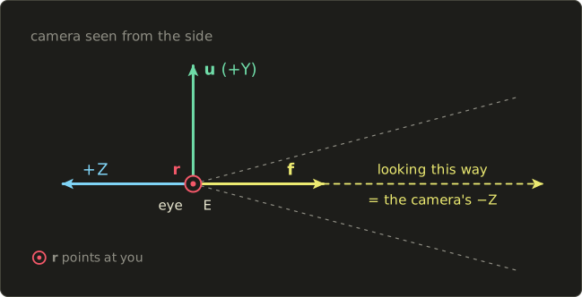
Now remember the convention of this whole series: in view space the camera looks down −Z.
With +X to the right and +Y up, a right-handed system puts +Z pointing out of the screen, towards you.
So "into the screen" is −Z, and the camera's own +Z axis points backwards, along .
You can check the handedness: is like , which points backwards, so .
Using the rule from the last section, the matrix that converts camera coordinates into world coordinates has the camera's axes and its position as columns:
This is the camera's world matrix, exactly like any other object's model matrix.
It's a rotation (the first three columns) followed by a translation to the eye: .
11.5 The view matrix and lookAt: the formula
But we don't want camera to world.
We have vertices in world space and we want to know where they are relative to the camera: world to camera.
That's the inverse:
This is the view matrix.
There's a neat way to think about it: the GPU never moves a camera.
Instead, the view matrix moves the whole world so that the camera ends up at the origin, looking down −Z.
Stepping the camera 1 m to the right is the same as sliding the entire world 1 m to the left.
We don't need the general 4×4 inverse here, because chapter 10 gave us the cheap rules: "socks and shoes" , a rotation's inverse is its transpose, and a translation's inverse is the opposite translation:
The rows of are , and .
Multiplying by first subtracts the eye, then the rows dot the result, so the translation column becomes :
Read it row by row and it makes sense: the new x of a point is "how far to the right of the eye is it", the new y is "how far above", and the new z is "how far behind" (negative means in front).
Of course nobody wants to type in , and by hand.
The lookAt function builds them from three easy things: where the camera is (), what it looks at (the target ), and roughly which way is up (, usually the world's ):
11.6 How lookAt works, step by step
Let me justify each of the three lines.
- Forward is the arrow from the eye to the target (chapter 2: target minus eye), normalized so it has length 1 (chapter 3).
- Right must be perpendicular to forward and to up, and a cross product (chapter 5) gives exactly a vector perpendicular to both. We normalize it because forward and the up hint are usually not perpendicular (a camera looking down at a slant), so the length of the cross product is , which is less than 1.
- True up is perpendicular to right and forward. It's already unit length, because and are unit vectors at 90° and . This is the camera's real up, tilted along with the camera, not the world's up.
Let's check the directions with the simplest camera: looking down −Z with up = +Y.
Then , which is +X, to the right.
And , which is up.
The order inside the cross products matters (chapter 5: swapping them flips the sign), and this order is the one that matches our right-handed system.
A worked example
Camera at , looking at the origin , up hint .
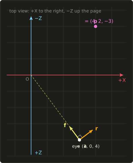
Step 1, forward.
Step 2, right. With the cross product formula and :
Its length is already (because this camera looks perfectly horizontally), so .
Step 3, true up.
Step 4, the translation column.
Step 5, assemble. Rows , , :
Step 6, check it.
The target (the origin) should be straight ahead at distance 5.
Multiplying just picks the last column: .
Straight ahead, 5 units away, exactly right.
The eye itself: , , , so the camera sits at the origin of view space.
Now a point :
So in view space is at : 5 units to the right, 2 up, and 5 ahead.
Keep this point in mind, in chapter 12 we'll find out which pixel it lands on.
When lookAt breaks
If the camera looks straight up or straight down, forward is parallel to the up hint.
Then is the zero vector (chapter 5: parallel vectors have a zero cross product).
Our normalize from chapter 3 returns the zero vector instead of dividing by zero, so and both become zero, the matrix squashes everything flat (its determinant is 0, chapter 10), and your screen goes blank or flickers.
The fixes are simple: never let the camera look exactly along the up hint (see pitch clamping below), or pass a different up hint for that case, like for a top-down map camera.
11.7 First-person and orbit cameras
First-person camera from yaw and pitch
In a first-person game you don't store a target point.
You store two angles that the mouse changes:
- yaw : turning left and right, a rotation around the world's up axis Y
- pitch : looking up and down, a rotation around the camera's right axis
Start with the forward direction , pitch it around X, then yaw it around Y, using rotateX and rotateY from chapter 8: .
The pitch step gives , and the yaw step then turns that around Y.
Multiplying it out gives:
It's always unit length, using from chapter 1 twice:
Worked example: yaw 60°, pitch 30°.
We need , , and .
Check: .
The camera looks left of −Z (because positive yaw is counter-clockwise seen from above, by the right-hand rule) and 30° upwards.
That also means that when the mouse moves right, yaw should decrease.
Clamping the pitch. At pitch ±90°, forward becomes , parallel to the world's up, which is exactly the broken case from the last section.
Past 90° the view flips upside down.
So every first-person camera clamps the pitch to a bit less than 90°.
Here is a small camera update function (forwardFromYawPitch is the formula above written as code, you'll find it in section 11.10):
struct FpsCamera {
  Vec3 eye{0, 2, 0};
  float yaw = 0.0f, pitch = 0.0f;
};

// mouseDx, mouseDy: how far the mouse moved this frame, in pixels
inline Mat4 updateFpsCamera(FpsCamera &cam, float mouseDx, float mouseDy, float sensitivity) {
  cam.yaw -= mouseDx * sensitivity;   // mouse right -> turn right
  cam.pitch -= mouseDy * sensitivity; // screen y grows downwards
  const float limit = radians(89.0f);
  if (cam.pitch > limit) cam.pitch = limit;
  if (cam.pitch < -limit) cam.pitch = -limit;

  Vec3 forward = forwardFromYawPitch(cam.yaw, cam.pitch);
  return lookAt(cam.eye, cam.eye + forward, {0, 1, 0});
}
A small tip for walking: move along forwardFromYawPitch(yaw, 0.0f), the forward direction without pitch.
Otherwise looking at the floor makes you walk slower, the same kind of bug as the diagonal movement bug from chapter 3.
The strafe direction is normalize(cross(forward, up)).
Orbit camera
Model viewers and strategy games often circle around a target instead.
Same two angles plus a distance , and the eye is placed behind the target, against the forward direction:
Then lookAt(eye, target, up) builds the view matrix.
Dragging the mouse changes yaw and pitch, the scroll wheel changes .
A negative pitch looks down, so the eye ends up above the target.
For example, target , , yaw 0 and pitch −30° give and : above and behind the target.
11.8 Use in graphics programming: P V M
Every vertex goes through the whole chain.
Reading right to left like always (chapter 7):
The three matrices change at different rates:
- is different for every object.
- changes once per frame, when the camera moves.
- changes only when the window is resized or the field of view changes.
Because matrix multiplication is associative (chapter 7), you can multiply some of them on the CPU and send fewer matrices.
A common setup sends once per frame and per object, because the shader usually needs the world position for lighting anyway.
Here is the straightforward version with all three:
struct Matrices {
  float4x4 model;
  float4x4 view;
  float4x4 proj;
};
ConstantBuffer<Matrices> matrices;

struct VertexOut {
  float4 position : SV_Position;
  float3 worldPos : TEXCOORD0;
};

[shader("vertex")]
VertexOut vertexMain(float3 position : POSITION) {
  VertexOut o;
  float4 world = mul(matrices.model, float4(position, 1.0));
  float4 viewPos = mul(matrices.view, world);
  o.position = mul(matrices.proj, viewPos);
  o.worldPos = world.xyz;
  return o;
}
#version 450
layout(set = 0, binding = 0) uniform Matrices {
mat4 model;
mat4 view;
mat4 proj;
};
layout(location = 0) in vec3 inPosition;
layout(location = 0) out vec3 outWorldPos;
void main() {
vec4 world = model * vec4(inPosition, 1.0);
vec4 viewPos = view * world;
gl_Position = proj * viewPos;
outWorldPos = world.xyz;
}struct Matrices {
float4x4 model;
float4x4 view;
float4x4 proj;
};
ConstantBuffer<Matrices> matrices;
struct VertexOut {
float4 position : SV_Position;
float3 worldPos : TEXCOORD0;
};
VertexOut vertexMain(float3 position : POSITION) {
VertexOut o;
float4 world = mul(matrices.model, float4(position, 1.0));
float4 viewPos = mul(matrices.view, world);
o.position = mul(matrices.proj, viewPos);
o.worldPos = world.xyz;
return o;
}A few more everyday uses of what we just built:
- Camera position for lighting. Specular highlights need the eye position in world space. It's the fourth column of , which is the camera's world matrix . Compute it on the CPU and send it as a uniform.
- Billboards. Particles and name tags should always face the camera. The first two rows of the view matrix are the camera's right and up in world space, so you can build the quad's corners from them.
- Skyboxes. The sky must never get closer when you walk. Copy the view matrix and replace its fourth column with , so only the rotation is left:
sky.c[3] = {0, 0, 0, 1}; - Fog and sorting. In view space, is the distance in front of the camera. It's handy for fog and for sorting transparent objects from back to front.
Here's the billboard function.
Notice the indexing difference from chapter 6: Slang and HLSL read a row as view[0], while GLSL indexes column first, so the same row is spread across view[0][0], view[1][0] and view[2][0].
float3 billboardCorner(float4x4 view, float3 center, float2 corner, float size) {
  float3 right = float3(view[0][0], view[0][1], view[0][2]);
  float3 up = float3(view[1][0], view[1][1], view[1][2]);
  return center + (corner.x * right + corner.y * up) * size;
}
vec3 billboardCorner(mat4 view, vec3 center, vec2 corner, float size) {
vec3 right = vec3(view[0][0], view[1][0], view[2][0]);
vec3 up = vec3(view[0][1], view[1][1], view[2][1]);
return center + (corner.x * right + corner.y * up) * size;
}float3 billboardCorner(float4x4 view, float3 center, float2 corner, float size) {
float3 right = float3(view[0][0], view[0][1], view[0][2]);
float3 up = float3(view[1][0], view[1][1], view[1][2]);
return center + (corner.x * right + corner.y * up) * size;
}11.9 Other uses
Changing reference frames is everywhere once you start looking:
- Robotics. Every joint, gripper and camera on a robot has its own frame. "Where is the cup, seen from the gripper?" is a change of basis. ROS keeps a whole tree of these frames in its tf library.
- AR and VR. The headset tracks your head's position and orientation and builds a view matrix from them every frame, one for each eye, shifted by half the distance between your eyes.
- GPS and drones. GPS gives positions in an Earth-centered frame. Drones and self-driving cars convert them into a local East-North-Up frame around a reference point, which is a rotation plus a translation.
- Astronomy. Star positions are given in equatorial, ecliptic or galactic coordinates, and fixed rotation matrices convert between them.
- Aircraft. Pilots and flight software use a body frame (forward, right wing, down) attached to the plane. Its orientation is described by yaw, pitch and roll, which brings us to chapter 13.
11.10 Code
Here is lookAt as it appears in linalg.hh.
Compare it line by line with section 11.5: rows , , , and the translation column , , .
// ビュー行列:カメラがeyeからtargetを見る。カメラは自分の-Z方向を向く。
// View matrix: camera at eye looking at target. The camera looks down its own -Z axis.
inline Mat4 lookAt(Vec3 eye, Vec3 target, Vec3 up) {
  Vec3 f = normalize(target - eye); // 前 / forward
  Vec3 r = normalize(cross(f, up)); // 右 / right
  Vec3 u = cross(r, f);             // 上 / up

  Mat4 m = Mat4::identity();
  m.at(0, 0) = r.x;  m.at(0, 1) = r.y;  m.at(0, 2) = r.z;  m.at(0, 3) = -dot(r, eye);
  m.at(1, 0) = u.x;  m.at(1, 1) = u.y;  m.at(1, 2) = u.z;  m.at(1, 3) = -dot(u, eye);
  m.at(2, 0) = -f.x; m.at(2, 1) = -f.y; m.at(2, 2) = -f.z; m.at(2, 3) = dot(f, eye);
  return m;
}
And a test program with the forwardFromYawPitch helper from section 11.7.
It also checks that the inverse of the view matrix (chapter 10) really is the camera's world matrix, by reading the eye position from its fourth column.
#include <cstdio>
#include "linalg.hh"

// yaw: turn around +Y, pitch: look up (+) or down (-). yaw = pitch = 0 looks down -Z.
inline Vec3 forwardFromYawPitch(float yaw, float pitch) {
  float cp = std::cos(pitch);
  return {-std::sin(yaw) * cp, std::sin(pitch), -std::cos(yaw) * cp};
}

static void printVec(const char *name, Vec4 v) {
  printf("%-8s (%6.3f, %6.3f, %6.3f, %6.3f)\n", name, v.x, v.y, v.z, v.w);
}

static void printMat(const Mat4 &m) {
  for (int row = 0; row < 4; ++row)
    printf("  [%6.3f %6.3f %6.3f %6.3f]\n", m.at(row, 0), m.at(row, 1), m.at(row, 2), m.at(row, 3));
}

int main() {
  // a camera at (3, 0, 4) looking at the origin
  Mat4 view = lookAt({3, 0, 4}, {0, 0, 0}, {0, 1, 0});
  printf("view matrix:\n");
  printMat(view);

  printVec("origin", view * Vec4{0, 0, 0, 1});
  printVec("eye", view * Vec4{3, 0, 4, 1});
  printVec("p", view * Vec4{4, 2, -3, 1});

  // the camera's world matrix is the inverse of the view matrix
  Mat4 camWorld = inverse(view);
  printVec("camPos", camWorld.c[3]);

  // first-person camera: yaw 60 degrees, pitch 30 degrees
  Vec3 f = forwardFromYawPitch(radians(60.0f), radians(30.0f));
  printf("forward  (%6.3f, %6.3f, %6.3f) length %.3f\n", f.x, f.y, f.z, length(f));

  Vec3 eye{0, 2, 0};
  Mat4 fps = lookAt(eye, eye + f, {0, 1, 0});
  printVec("ahead", fps * Vec4{eye.x + 2 * f.x, eye.y + 2 * f.y, eye.z + 2 * f.z, 1});
  return 0;
}
Compile it like before with g++ -std=c++20 main.cc -o main and run it:
view matrix:
  [ 0.800  0.000 -0.600 -0.000]
  [ 0.000  1.000  0.000 -0.000]
  [ 0.600 -0.000  0.800 -5.000]
  [ 0.000  0.000  0.000  1.000]
origin   ( 0.000,  0.000, -5.000,  1.000)
eye      ( 0.000,  0.000,  0.000,  1.000)
p        ( 5.000,  2.000, -5.000,  1.000)
camPos   ( 3.000,  0.000,  4.000,  1.000)
forward  (-0.750,  0.500, -0.433) length 1.000
ahead    ( 0.000,  0.000, -2.000,  1.000)
Don't worry about the -0.000 entries.
Floating point numbers have a sign bit even for zero, so comes out as a "negative zero", which compares equal to 0.
Depending on your compiler you may see 0.000 there instead.
The last line is a nice check: a point 2 units along the camera's forward direction ends up at , straight down −Z.
In the next chapter we'll put a projection matrix in front of the view matrix and combine them into one view-projection matrix, like this:
Mat4 viewProj = perspectiveGl(radians(60.0f), 16.0f / 9.0f, 0.1f, 100.0f) * view;11.11 Summary
- A space is a choice of origin and axes. A vertex travels object → world → view → clip → NDC → screen, through M, V, P, the divide by w and the viewport transform.
- A matrix whose columns are frame A's axes (and origin) written in frame B converts A to B. Its inverse converts B to A.
- For an orthonormal basis the inverse is the transpose, because the new coordinates are just dot products with the axes.
- The camera is an object with eye and axes right, up, forward. It looks down its own −Z.
- The view matrix is the inverse of the camera's world matrix: rows , , and translation , , .
lookAtbuilds forward from target minus eye, right fromcross(f, up)and true up fromcross(r, f). It breaks when forward is parallel to up.- Yaw and pitch give a forward vector with sin and cos. Clamp the pitch below 90°.
- Every vertex is transformed by , applied right to left.
11.12 Challenges
- ★ A 2D frame has axes and . A point has coordinates in this frame: what are its old coordinates? Then convert the old point into the new frame.
- ★ Check that , , are orthonormal and right-handed (), then find the coordinates of in this basis.
- ★ Build the view matrix for eye , target and up by hand. Write down the length of before normalizing it, and explain why it isn't 1.
- ★ Compute
forwardFromYawPitchfor yaw 90° and pitch −45°, with exact values (use ). Which way is the camera looking? - ★★ Write
orbitEye(Vec3 target, float distance, float yaw, float pitch). For target , distance 4, yaw 0 and pitch −30° it should return about , andlookAt(eye, target, {0, 1, 0}) * Vec4{0, 1, 0, 1}should print . - ★★ Write
void cameraAxes(const Mat4 &view, Vec3 &right, Vec3 &up, Vec3 &forward)that reads the three axes from the rows of a view matrix. For the camera in section 11.6 it should print right , up and forward . - ★★★
lookAtcan't roll the camera (tilt the horizon), because it always uses the world's up. Add a roll angle: after computing and , rotate them inside their own plane with the 2D rotation from chapter 8. What happens if you pass up instead, and why?
コメント(0)
まだコメントはありません。
ログインするとコメント出来ます。