19. Projection and Rasterization in Depth
Welcome to Part 2.
Part 1 (chapters 1 to 18) walked through the whole syllabus of the CG Engineer Certification, Expert level, at a beginner-friendly depth.
Part 2 (chapters 19 to 29) goes beyond the syllabus.
It takes the topics that Part 1 could only sketch and works them out properly: the projection and rasterization details in this chapter, then anti-aliasing and transparency, mesh processing and signed distance fields, physically based shading, Monte Carlo rendering, real-time shadows and global illumination, advanced animation and physics, HDR and image processing, volume rendering, and finally modern GPUs and neural rendering.
How does Part 2 relate to Part 1?
Every Part 2 chapter starts from something Part 1 introduced, links back to the section where it was introduced, and keeps the same terms and notation.
Where Part 1 said "Part 2 covers this", the promise is kept in the chapter that owns the topic.
Expect more derivations, in the same style: intuition first, then the formula, then worked numbers.
You don't need Part 2 to pass the exam; the mini-exam in chapter 30 tests the syllabus.
But many exam answers become obvious once you know why they are true, and that's what this part is for.
Where a topic ties back to a syllabus item, an "Exam points" list says which one.
This chapter opens up the two boxes of the pipeline that Part 1 treated as black boxes: the projection matrix and the rasterizer.
In chapter 6 I promised that "Part 2 derives all of this", and chapters 5 and 10 left depth precision, reversed Z and the depth offset for decals for later.
Here's the plan:
- The perspective matrix derived for any frustum and any depth convention (OpenGL, Vulkan/Direct3D, reversed), with the y flip, the infinite far plane and the orthographic case.
- The inverse projection: getting the camera-space position back from a pixel and its depth.
- Clipping in homogeneous clip space: what goes wrong without it, a worked near-plane clip, guard bands.
- Depth precision: where it goes, fixed point versus floating point, reversed Z, logarithmic depth, and depth bias.
- The rasterizer: edge functions, the top-left rule, fixed-point snapping, tiled traversal, perspective-correct interpolation derived, derivatives in 2×2 quads, early-Z and hierarchical Z.
You need Linear Algebra chapter 12 (projection), chapter 10 (inverse matrices) and section 6.9 of chapter 6 (edge functions); everything else is built here.
19.1 The perspective matrix, for any convention
What the matrix has to do
Linear Algebra chapter 12 derived perspectiveGl and perspectiveVk for a symmetric frustum.
Let's redo it in a way that covers every variant at once.
The camera looks down −z, so a point in front of it has a positive distance .
The matrix has four jobs, one per row:
- the bottom row copies the distance into , so that the GPU's perspective division divides by it: ;
- the x and y rows produce values that land exactly on ±1 at the edges of the frustum after that division;
- the z row produces a depth that lands on the chosen values at the near and far planes;
- and all of it must be linear in , because it's a matrix.
The x and y rows: an off-center frustum
Describe the frustum by its near plane at distance and the rectangle it cuts out of that plane: from to in x and from to in y.
A point projects onto the near plane at (similar triangles, chapter 5, section 5.9).
We want to become −1 and to become +1, which is the 1D window–viewport map of chapter 4:
The factor is the perspective division, so the matrix only has to produce the bracket:
For a symmetric frustum, and , the z terms vanish.
With the vertical field of view we have , so , and with the aspect ratio the x entry is : exactly the entries of perspectiveGl.
Off-center frustums are not exotic: VR headsets render each eye with one, a wall of monitors gives each monitor its own piece of one big frustum, and temporal anti-aliasing shifts the frustum by a fraction of a pixel every frame (chapter 20).
To move the image by in NDC, add to , that is, put into row 0, column 2.
Half a pixel on an 800-pixel-wide screen is .
The z row: depth has to follow 1/z
The z row can only be : it must not depend on x or y (all points at the same distance get the same depth), and it can't contain anything but a linear combination of z and 1.
After the division:
This is the whole story of the depth buffer's non-linearity.
Whatever and we choose, the stored depth is an affine function of .
It isn't a design decision somebody made; it's forced by the requirement that the projection be one 4×4 matrix followed by a division.
And there's a good side to it: we'll see in section 19.5 that , and so the depth, is linear on the screen across a triangle, which is exactly what lets the rasterizer interpolate depth with plain screen-space weights.
One formula for every depth convention
Say the near plane should get the depth and the far plane .
Two conditions, two unknowns:
Multiply out, and , and subtract the first from the second: .
Put back into the first equation:
Now every convention is one substitution away:
| Convention | , | ||
|---|---|---|---|
| OpenGL | −1, 1 | ||
| Vulkan, Direct3D, Metal | 0, 1 | ||
| reversed Z | 1, 0 |
The first two rows are the entries of perspectiveGl and perspectiveVk (Linear Algebra chapter 12 writes the Vulkan ones as and , the same numbers).
The third row, reversed Z, puts the near plane at 1 and the far plane at 0; section 19.4 explains why anyone would want that.
Worked example. The vertex of chapter 6, section 6.2, is at camera position , so , with and :
- OpenGL: , , , , and the depth buffer stores .
- Vulkan: , , depth , the same value.
- Reversed: , , , depth .
In general the reversed depth is exactly one minus the standard 0 to 1 depth: same planes, numbered backwards.
The y flip
The three APIs also disagree about which way y points.
OpenGL, Direct3D and Metal have y up in NDC; Vulkan has y down.
For Vulkan you either negate the y row (that's the in perspectiveVk) or keep the y row and give the viewport a negative height, never both (Linear Algebra chapter 12, section 12.7).
The flip mirrors the image, and mirroring swaps clockwise and counter-clockwise, so check the front-face setting used for back-face culling against it.
The infinite far plane
What happens if we let ?
Divide numerator and denominator by and let :
| Convention | depth at distance | ||
|---|---|---|---|
| OpenGL | −1 | ||
| Vulkan, Direct3D | −1 | ||
| reversed Z | 0 |
Nothing breaks: the far plane simply moves to infinity, and a point at infinity (a direction, with homogeneous coordinate 0 in camera space) lands exactly on depth 1, or 0 for reversed Z.
The reversed infinite version is the most elegant matrix in this chapter: its z row is constant, , so the stored depth is exactly .
For our vertex at distance 4 with that's .
Infinite projections make the z-fail shadow volumes of chapter 11 robust (their caps at infinity are never cut off) and suit big outdoor scenes.
Orthographic projection in the same frame
An orthographic projection has bottom row , so and nothing is divided.
Its z row is therefore linear in the distance, and the same two conditions give
For OpenGL, and , the entries of orthographicGl.
With linear depth, every distance gets the same precision, and a depth format with a uniform step (a fixed-point one) suits it best; reversing it gains nothing worth mentioning.
That's why orthographic shadow maps for the sun (chapter 11) don't suffer from the distance problem of section 19.4.
19.2 The inverse projection
Why go backwards?
Many effects start from the depth buffer and need to know where in 3D a pixel is.
Deferred shading lights a G-buffer that stores normals and colors but not positions (chapter 17), screen-space ambient occlusion marches through the depth buffer (chapter 24), and fog and projected decals need the position under each pixel.
Reconstructing it from the depth costs a few instructions instead of 12 bytes per pixel.
Undoing the matrix
The perspective matrix has the shape
(multiply them to check: the third row of times the last two columns of gives and ).
exists as long as , which is true for every perspective matrix above ( contains the factor ).
To go back from a pixel, first undo the viewport transform to get NDC, then multiply by , and finally divide by the resulting , because gives back a homogeneous point.
Worked example. In chapter 6 our vertex landed on pixel of an 800×600 window (rows counted from the top) with the depth 0.825 (OpenGL, , , 90°, aspect 4/3).
Undo the viewport:
With , , , , the last row of is :
Divide by : , the camera position we started from.
Notice the in the third component: always produces before the division, and the division by turns it into .
The shortcut: linear depth times a ray
Written out, the same computation is only three formulas.
First the distance from the depth (solve for ):
With our numbers: .
Then x and y from the NDC position: , so
Geometrically: is the pixel's ray direction scaled so that its z is −1, and the position is that ray times the distance.
Engines often compute that ray once per pixel (or per vertex of a full-screen triangle, letting the rasterizer interpolate it) and then only need the distance.
For the reversed infinite projection the distance is simplest of all: the depth is , so .
Code
Here are the reversed and the reversed infinite matrices, written in the style of linalg.hh (they're not part of the header), applied to the vertex of chapter 6, followed by the reconstruction with the header's inverse:
#include <cstdio>
#include "linalg.hh"

// Reversed Z, depth 0..1 (Vulkan/Direct3D style, y down): near -> 1, far -> 0.
inline Mat4 perspectiveVkReversed(float fovY, float aspect, float n, float f) {
  float t = 1.0f / std::tan(fovY * 0.5f);
  Mat4 m;
  m.at(0, 0) = t / aspect;
  m.at(1, 1) = -t;
  m.at(2, 2) = n / (f - n);
  m.at(2, 3) = (f * n) / (f - n);
  m.at(3, 2) = -1.0f;
  return m;
}

// Reversed Z with the far plane at infinity: the stored depth is exactly n / distance.
inline Mat4 perspectiveVkInfiniteReversed(float fovY, float aspect, float n) {
  float t = 1.0f / std::tan(fovY * 0.5f);
  Mat4 m;
  m.at(0, 0) = t / aspect;
  m.at(1, 1) = -t;
  m.at(2, 3) = n;
  m.at(3, 2) = -1.0f;
  return m;
}

void show(const char *name, const Mat4 &p, Vec4 v) {
  Vec4 c = p * v;
  printf("%-18s clip (%g, %g, %g, %g)  z/w %g\n", name, c.x, c.y, c.z, c.w, c.z / c.w);
}

int main() {
  const float pi = 3.14159265f;
  Vec4 cam{2, 1, -4, 1}; // the vertex of chapter 6 in camera space
  show("OpenGL", perspectiveGl(pi / 2, 4.0f / 3.0f, 1, 11), cam);
  show("Vulkan", perspectiveVk(pi / 2, 4.0f / 3.0f, 1, 11), cam);
  show("reversed", perspectiveVkReversed(pi / 2, 4.0f / 3.0f, 1, 11), cam);
  show("infinite reversed", perspectiveVkInfiniteReversed(pi / 2, 4.0f / 3.0f, 1), cam);

  // back from pixel (550, 225) of an 800x600 window with depth 0.825 (OpenGL depth range 0..1)
  float px = 550, py = 225, depth = 0.825f;
  Vec4 ndc{2 * px / 800 - 1, 1 - 2 * py / 600, 2 * depth - 1, 1};
  Vec4 v = inverse(perspectiveGl(pi / 2, 4.0f / 3.0f, 1, 11)) * ndc;
  printf("P^-1 * ndc = (%g, %g, %g, %g)\n", v.x, v.y, v.z, v.w);
  printf("camera     = (%g, %g, %g)\n", v.x / v.w, v.y / v.w, v.z / v.w);
  return 0;
}
OpenGL             clip (1.5, 1, 2.6, 4)  z/w 0.65
Vulkan             clip (1.5, -1, 3.3, 4)  z/w 0.825
reversed           clip (1.5, -1, 0.7, 4)  z/w 0.175
infinite reversed  clip (1.5, -1, 1, 4)  z/w 0.25
P^-1 * ndc = (0.5, 0.25, -1, 0.25)
camera     = (2, 1, -4)
In a shader the shortcut is what you'd write.
For a Vulkan renderer with reversed infinite Z, a texture coordinate uv from 0 to 1 across the screen (y down, like Vulkan's NDC) and scale , the two diagonal entries of the matrix:
// depth: reversed infinite Z, so depth = n / distance
float3 viewPosFromDepth(float2 uv, float depth, float n, float2 scale) {
  float d = n / depth;                      // distance in front of the camera
  float2 ndc = uv * 2.0 - 1.0;              // Vulkan NDC, y down
  return float3(ndc.x * d / scale.x, -ndc.y * d / scale.y, -d);
}
// depth: reversed infinite Z, so depth = n / distance
vec3 viewPosFromDepth(vec2 uv, float depth, float n, vec2 scale) {
float d = n / depth; // distance in front of the camera
vec2 ndc = uv * 2.0 - 1.0; // Vulkan NDC, y down
return vec3(ndc.x * d / scale.x, -ndc.y * d / scale.y, -d);
}// depth: reversed infinite Z, so depth = n / distance
float3 viewPosFromDepth(float2 uv, float depth, float n, float2 scale) {
float d = n / depth; // distance in front of the camera
float2 ndc = uv * 2.0 - 1.0; // Vulkan NDC, y down
return float3(ndc.x * d / scale.x, -ndc.y * d / scale.y, -d);
}
The minus sign on y undoes the of the Vulkan matrix.
The background, where nothing was drawn, has the cleared depth 0 and would give an infinite distance, so real code tests for it first.
19.3 Clipping in homogeneous clip space
What goes wrong without it
Section 6.3 of chapter 6 clipped a segment that went behind the camera and showed that dividing first sends the far end to the wrong place.
Let's look at the reason more closely and then clip a whole triangle.
The division by is the culprit.
A point in front of the camera has ; a point exactly in the plane of the eye has and would be divided by zero; a point behind the camera has , and the division flips the signs of its x and y, so it lands mirrored through the center of the screen.
A segment from a point in front to a point behind passes through , where its projection runs off to infinity; after the division its two ends are connected the "wrong way round", through the part of the screen it doesn't cover, and not through infinity where it really goes.
The rasterizer, which only knows the three projected corners, fills the wrong region.
Clipping before the division removes every point with less than the near distance, so the division never sees .
Near-plane clipping, worked
Take the OpenGL matrix of chapter 6 again (90°, aspect 4/3, , : , , , ).
A floor triangle at height reaches under the camera: , and , with C one unit behind the eye.
Each vertex also carries a texture coordinate: , , .
Their clip coordinates:
The OpenGL near plane is , so the signed value to test is :
C is outside, A and B are inside.
Sutherland–Hodgman (section 6.3) walks the edges A→B→C→A:
- A→B: A is inside, output A; B is inside too, so no crossing.
- B→C: output B. B is inside and C outside, so the edge crosses at : output .
- C→A: C is outside, output nothing; the edge crosses at from C: output .
The triangle has become the quadrilateral , which the GPU draws as two triangles.
Both new vertices have , so their NDC depth is −1: they lie exactly on the near plane.
The attributes are interpolated with the same : and .
Is linear interpolation in clip space right for attributes?
Yes: clip coordinates are a linear function of camera coordinates (one matrix multiplication), so the point at parameter on the clip-space segment is the point at the same on the camera-space segment, and an attribute that varies linearly over the 3D triangle has its value there.
As a check, in camera space: on the near plane .
Only after the division does linear interpolation stop being correct, which is the subject of section 19.5.
Divide and compare with the naive version:
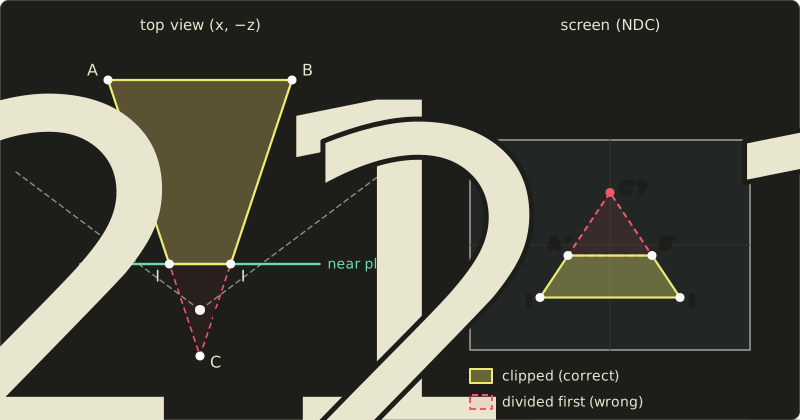
The clipped quad has NDC corners , , , : a floor that widens towards the bottom of the screen, as a floor reaching under your feet should.
Dividing C first gives , above the center: the rasterizer would draw a triangle pointing up into the sky.
The clipper itself is the Sutherland–Hodgman loop of chapter 6 with as the inside test and every attribute interpolated with the same .
With one vertex outside, a triangle becomes a quadrilateral (two triangles); with two outside it stays a triangle.
For the Vulkan and Direct3D convention the near plane is , so the signed value is simply ; for reversed Z it is , because there the near plane is .
Guard bands, depth clamp and clipping-free rasterization
Clipping creates new vertices, and new vertices cost time, so GPUs avoid it where they can.
Against the four side planes they mostly don't clip at all: the rasterizer simply never visits pixels outside the viewport (with the bounding box and tiles of section 19.5 that's free).
The limit is the rasterizer's number format: positions are converted to fixed point (section 19.5), so a vertex may be far outside the screen, but not arbitrarily far.
The region the rasterizer can still represent is the guard band (ガードバンド), much larger than the viewport; only the rare triangle that sticks out beyond it is clipped geometrically.
The near plane can't be handled this way, because the trouble there is , not a large coordinate.
For the near and far planes there is one more option: OpenGL and Vulkan offer depth clamping (GL_DEPTH_CLAMP, Vulkan's depthClampEnable), which turns off near and far clipping and instead clamps the depth into range.
Shadow maps use it so that casters between the light and the shadow map's near plane are not lost: they're "pancaked" onto the near plane and still cast their shadow.
(It's even possible to skip clipping altogether by setting up the edge functions of section 19.5 directly from the homogeneous coordinates, as Olano and Greer described in 1997; the image is the same.)
19.4 Depth precision
Where the precision goes
Section 19.1 proved that the stored depth is affine in .
For the 0 to 1 range,
The second formula, the inverse, tells us where each depth value lies.
With and (our chapter 6 setup), the planes where the stored depth crosses 0.1, 0.2, …, 0.9 are at the distances
Half of all depth values are used up before distance , and the last 10% of the values have to cover everything from 5.5 to 11:
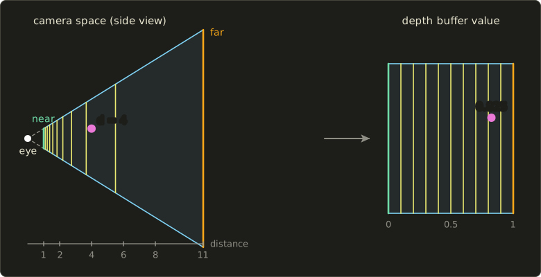
How much distance does one step of the stored value cover?
Differentiate: , so a step is a distance step of
That's the formula of chapter 10, section 10.3: the step grows with the square of the distance, and it is inversely proportional to .
What chapter 10 assumed silently is that is the same everywhere.
That's true for some depth formats and not for others.
Fixed point and floating point
Depth buffers come in two families:
- Fixed-point (UNORM) formats store an integer from 0 to meaning . The step is the same everywhere: for 16 bits, for 24 bits (usually packed with an 8-bit stencil value).
- Floating-point formats (32-bit float,
D32_SFLOATin Vulkan) store a sign, an 8-bit exponent and a 23-bit mantissa. The step depends on the value: between and it is . So between 0.5 and 1 the step is , the same as 24-bit fixed point, but between 0.001 and 0.002 it is about , and it keeps shrinking towards 0.
In short, a float has a constant relative precision: the step is always between and of the value itself.
Now put the two non-linearities together.
With the standard mapping, far away is where is close to 1, and close to 1 a float is no better than 24-bit fixed point.
All the extra precision of the float sits near , right in front of the near plane, where the mapping has already given us more precision than we need.
A 32-bit float buffer with standard Z is a waste of 8 bits.
Reversed Z
Now flip the mapping: near plane at 1, far plane at 0.
Far away, where gives coarse depth steps, the stored values are close to 0, where the float's steps are tiny.
The two effects cancel, and we can see exactly how well with the reversed infinite projection, where :
The distance step is a constant fraction of the distance, between about and of it, at every distance, and it doesn't even depend on any more.
(With a finite far plane the same derivation gives , slightly better still near .)
That's the same kind of precision a float has for the distance itself, which is the best you can hope for.
Worked comparison. The setup of chapter 10, m and m, with the actual distance between neighboring stored values (computed by taking a stored value and the next representable one and converting both back to distances):
| Distance | 16-bit UNORM | 24-bit UNORM | float32, standard | float32, reversed |
|---|---|---|---|---|
| 1 m | 0.15 mm | 0.6 µm | 0.6 µm | 0.07 µm |
| 10 m | 15 mm | 0.06 mm | 0.06 mm | 0.9 µm |
| 100 m | 1.55 m | 6.0 mm | 6.0 mm | 5.8 µm |
| 500 m | 38 m | 15 cm | 15 cm | 18 µm |
Check one by hand.
At 100 m with 24-bit fixed point: m, the 6 mm of chapter 10.
Reversed: , which lies between and , so the float step is ; divided by the slope that's m.
About a thousand times finer than 24 bits at 100 m, and the advantage grows with the distance.
The plot shows the whole range (the saw teeth of the reversed curve are the float's exponent steps):
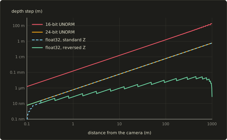
The storage format isn't the only source of error (the vertex shader's float arithmetic rounds too, and with the standard mapping divides two nearly equal numbers), but reversed Z helps there as well: with the infinite version is exact.
And with reversed float depth the near plane hardly matters any more, which is why engines that use it can afford a near plane of a few centimeters.
Setting it up
Reversed Z needs four things to agree:
- a floating-point depth format (
D32_SFLOATin Vulkan,DXGI_FORMAT_D32_FLOATin Direct3D,GL_DEPTH_COMPONENT32Fin OpenGL); - the reversed projection matrix of section 19.1 (finite or infinite);
- the depth buffer cleared to 0 instead of 1;
- the depth test flipped to greater (or greater-or-equal) instead of less.
It also needs a 0 to 1 depth range.
Vulkan, Direct3D and Metal have that by default.
OpenGL's default range is −1 to 1, and there reversing gains nothing: the far values end up near , where floats are coarse, and the conversion to the stored value then adds 1 to them, which wipes out the small differences before they reach the buffer.
Since OpenGL 4.5, glClipControl(GL_LOWER_LEFT, GL_ZERO_TO_ONE) switches OpenGL to the 0 to 1 range.
Everything else that reads depth must flip too: shadow-map comparisons, hierarchical Z (section 19.5), the polygon offset (below), and the "is this the background" test of section 19.2.
You'll work with depth testing yourself in OpenGL chapter 15.
Logarithmic depth, briefly
Another way to get a constant relative precision is to store the logarithm of the distance, for example
Then , and a uniform step is a distance step , again proportional to the distance.
With 24-bit fixed point, and : , so , or 0.055 mm at 100 m.
That's about a hundred times better than standard 24-bit depth at 100 m, but about ten times worse than reversed float, and it has a price: a logarithm can't come out of a projective matrix, so the depth isn't linear on the screen any more.
Written per vertex, it's interpolated wrongly across large triangles; written per fragment (gl_FragDepth, SV_Depth), it disables the early depth test of section 19.5.
Where reversed float depth is available, it's usually the better choice.
Depth bias and polygon offset
Even perfect precision can't separate two surfaces that are in the same plane.
A decal (a bullet hole, a road marking, a poster) is drawn as a second polygon exactly on top of the wall, and the two triangles' depths are interpolated from different vertices with different rounding, so each pixel picks a winner at random: z-fighting at any distance.
Shadow acne in chapter 11 (section 11.4) is the same problem between a surface and its own depth in the shadow map.
The hardware fix is a depth bias (デプスバイアス), called polygon offset in OpenGL: a value added to every fragment's depth of a polygon,
optionally clamped to a maximum.
is the polygon's depth slope in window space (how much its depth changes per pixel; the specifications define it with the square root of the sum of squares and allow this max as an approximation), and is the smallest resolvable difference of the depth format: (or up to twice that) for an N-bit fixed-point format, and for a float format , where is the largest exponent of the polygon's depth values.
The parameters are glPolygonOffset(factor, units) in OpenGL, depthBiasSlopeFactor, depthBiasConstantFactor and depthBiasClamp in Vulkan, and SlopeScaledDepthBias, DepthBias and DepthBiasClamp in Direct3D.
Why a slope term?
Because the rounding differences between two coplanar triangles are proportional to how fast the depth changes across a pixel.
Worked example. The floor of section 19.5's mipmap example below, seen from 1 m above it at a distance of about 9.8 m, with , and a 24-bit buffer.
One pixel row up the screen moves the floor point from m to m, so the stored depth changes by
The constant term alone, , is 5,600 times smaller: with the slope per meter between these two distances, one unit of it moves the decal by only 0.06 mm, too little to beat rounding differences of a fraction of .
A slope factor of 1 moves it by , about 0.31 m in distance, the depth range a single pixel of this floor spans.
That stops the flicker, but an object standing less than 0.31 m behind the decal (along the view ray) could now be overdrawn by it; that's what the clamp is for, and why engines often project decals in screen space instead, using the reconstructed positions of section 19.2.
Mind the sign.
With standard Z, nearer means smaller, so a decal needs a negative offset (glPolygonOffset(-1, -1) is a classic), while a shadow map needs a positive one to push the stored depths away; with reversed Z both signs flip.
19.5 Rasterization in depth
Edge functions are linear functions
Section 6.9 of chapter 6 introduced the edge function of a directed edge , , positive to the left of the edge (with y up).
Multiply it out and it's an ordinary linear function of the pixel position:
Its zero set is the line through the edge, and is a normal of that line pointing into the triangle.
For the chapter 6 triangle , , :
At the pixel center these give , and , the values of chapter 6.
Add the three functions: the x and y terms cancel and is left, which is , twice the area.
That's why the three barycentric coordinates always sum to 1.
Linearity is what makes rasterization cheap.
Going one pixel to the right adds , one pixel up adds , and pixels to the right add .
Along the row , starts at 42 at and then goes 36, 30, 24, 18, … one addition each.
Juan Pineda proposed exactly this formulation for parallel hardware in 1988: every pixel's test is independent, so many pixels can be tested at once by adding different multiples of and .
The top-left rule on shared edges
Chapter 6 stated the top-left rule and applied it to one triangle.
Its real job is between triangles, so let's test it where it matters: a 6 × 6 square from to , split along its diagonal into (lower right) and (upper left), both counter-clockwise.
The corners are placed on pixel centers on purpose: 7 centers lie on each side and 7 on the diagonal, the worst possible case.
In a mesh, the other side of every edge belongs to a neighbor, so a correct rule must give the square exactly the 36 pixels of its area.
Classify the edges (y up, counter-clockwise: a left edge goes down, a top edge is horizontal and goes left):
- : P→Q goes right (bottom edge, no), Q→R goes up (right edge, no), R→P goes down (left edge, yes).
- : P→R goes up (right edge, no), R→S is horizontal and goes left (top edge, yes), S→P goes down (left edge, yes).
The shared diagonal is a left edge of and a right edge of , so its 7 centers go to , never to both.
The left side and the top side of the square are owned; the right side and the bottom side are left to the neighbors.
Even the corners come out right: S (top-left corner) lies on two owned edges of and is drawn, while P, Q and R each lie on at least one edge that isn't owned and are left to the neighboring squares.
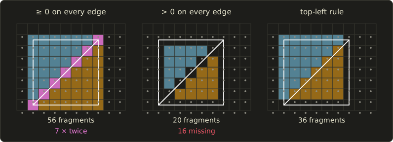
The counts (from the program below and the figure script):
- "≥ 0" everywhere: each triangle takes 28 centers, 56 fragments for a 36-pixel square, and the 7 diagonal pixels are drawn twice (wrong for transparency and wasted work).
- "> 0" everywhere: 10 + 10 = 20 fragments; the 5 interior diagonal centers belong to nobody (a crack), and in a mesh the 24 centers on the square's sides would be cracks too.
- Top-left: 15 + 21 = 36, every pixel exactly once.
The Vulkan specification only requires that a sample on an edge shared by two polygons is covered by exactly one of them, and OpenGL says the same; Direct3D fixes the top-left rule as the way to achieve it.
One more detail: Direct3D defines it in its own screen space with y pointing down, where "top" means the smallest y.
With y up, as here and in chapter 6, the same rule reads as above.
Sub-pixel precision and fixed-point snapping
The top-left rule depends on deciding whether exactly, and on the two triangles of a shared edge seeing exactly opposite values, .
In floating point neither is guaranteed: subtracts from while subtracts , and the products round differently.
Here's a real case in 32-bit floats: the edge from to and the pixel center .
The exact value of is about (the center is just to the right of the edge, so only the neighbor should draw it), but in float32 comes out as and as .
Both triangles see a positive value and both draw the pixel.
So rasterizers don't use floats for this.
After the viewport transform, each vertex position is snapped to a fixed-point grid, and the edge functions are evaluated with integers, which are exact.
Direct3D requires 16.8 fixed point (8 fractional bits, positions in steps of 1/256 pixel, rounded to the nearest); Vulkan reports the number of fractional bits of a device as subPixelPrecisionBits (at least 4).
Worked example. A vertex at px becomes , which is px: it moved by px, less than the maximum error px of rounding to 1/256.
The integers get big (an edge function multiplies two coordinate differences: with 4096 pixels and 8 fractional bits, products up to ), which is one reason the guard band can't be infinite.
Snapping has visible side effects too.
A tiny triangle can collapse to zero area (and then it's dropped) or even flip its winding; long thin triangles shift slightly; and since every vertex is snapped once, the same vertex always lands on the same grid point, which is what keeps shared edges watertight.
With integers, the top-left rule becomes a constant: if an edge isn't top-left, subtract 1 (one unit of the grid) from its , and the test is a plain for all three edges.
Here's that rasterizer, with snapping and incremental evaluation, on the square example:
#include <cmath>
#include <cstdint>
#include <cstdio>
#include "linalg.hh"

const int SUB = 256; // 8 fractional bits: positions in 1/256 pixel

struct IPoint {
  int64_t x, y;
};

IPoint snap(Vec2 p) { return {std::llround(p.x * SUB), std::llround(p.y * SUB)}; }

// Edge function as a linear function E(x, y) = A x + B y + C (y up, counter-clockwise inside)
struct Edge {
  int64_t A, B, C;
};

Edge makeEdge(IPoint a, IPoint b) {
  Edge e{a.y - b.y, b.x - a.x, a.x * b.y - a.y * b.x};
  // top-left rule: a left edge goes down, a top edge is horizontal and goes left.
  // Other edges must not own centers with E == 0, so we subtract 1 (one unit of SUB * SUB).
  bool topLeft = b.y < a.y || (b.y == a.y && b.x < a.x);
  if (!topLeft) e.C -= 1;
  return e;
}

int rasterize(Vec2 v0, Vec2 v1, Vec2 v2, char mark, char grid[8][10]) {
  IPoint a = snap(v0), b = snap(v1), c = snap(v2);
  Edge e[3] = {makeEdge(b, c), makeEdge(c, a), makeEdge(a, b)};
  int count = 0;
  for (int y = 0; y < 8; ++y) {
    // value at the first pixel center of the row, then add A per pixel (incremental evaluation)
    int64_t px = SUB / 2, py = y * SUB + SUB / 2;
    int64_t w[3];
    for (int k = 0; k < 3; ++k) w[k] = e[k].A * px + e[k].B * py + e[k].C;
    for (int x = 0; x < 10; ++x) {
      if (w[0] >= 0 && w[1] >= 0 && w[2] >= 0) {
        grid[y][x] = mark;
        ++count;
      }
      for (int k = 0; k < 3; ++k) w[k] += e[k].A * SUB;
    }
  }
  return count;
}

int main() {
  char grid[8][10];
  for (auto &row : grid)
    for (char &ch : row) ch = '.';
  Vec2 p{1.5f, 0.5f}, q{7.5f, 0.5f}, r{7.5f, 6.5f}, s{1.5f, 6.5f};
  int n1 = rasterize(p, q, r, '1', grid); // lower-right triangle
  int n2 = rasterize(p, r, s, '2', grid); // upper-left triangle, shares the diagonal p-r
  for (int y = 7; y >= 0; --y) printf("%.10s\n", grid[y]);
  printf("triangle 1: %d, triangle 2: %d, total %d\n", n1, n2, n1 + n2);
  return 0;
}
..........
.222222...
.222221...
.222211...
.222111...
.221111...
.211111...
..........
triangle 1: 15, triangle 2: 21, total 36
Traversal: bounding box and tiles
Which pixels does the rasterizer test?
The simplest answer is every pixel center in the triangle's bounding box, as in chapter 6.
That's fine for fat triangles, but a long thin one is a disaster: the triangle , , has an area of pixels, and its bounding box has , so nine tests out of ten are wasted.
GPUs therefore walk the screen in tiles, for example 4 × 4 or 8 × 8 pixels, and test a whole tile against each edge first.
Because an edge function is linear, its largest and smallest values over a rectangle are at two of the corners (which two depends only on the signs of and ).
That gives three cases per tile:
- Trivial reject: some edge is negative at all four corners. No pixel of the tile can be inside; skip it.
- Trivial accept: all three edges are non-negative at all four corners. Every pixel is inside; fill the tile without any per-pixel test.
- Partial: anything else. Test each pixel of the tile as before.
Worked example. A 40 × 24 pixel screen with 4 × 4 tiles (60 tiles) and the triangle , , , with area 382 pixels:
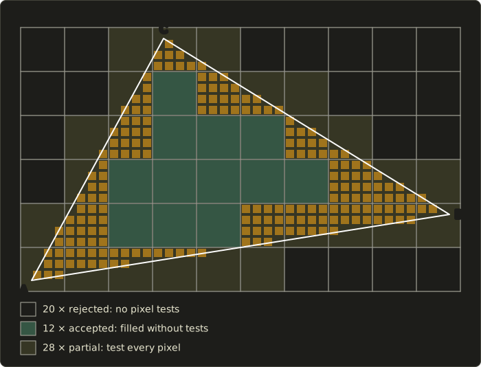
20 tiles are rejected with one corner test each, 12 tiles (192 pixels) are filled without testing a single pixel, and only the 28 partial tiles need per-pixel tests: tests, instead of for the bounding box.
381 pixel centers end up covered, very close to the area 382, as they should.
Real hardware does this hierarchically (large tiles, then smaller ones) and tests a tile's pixels in parallel.
Tile-based GPUs (most mobile ones, chapter 17) go one step further and sort all triangles into screen tiles before rasterizing, so that each tile's color and depth stay in fast on-chip memory.
Barycentric coordinates and attribute planes
Dividing the edge functions by the doubled area gives the barycentric coordinates (section 6.9), and since the edge functions are linear in and , so are the barycentric coordinates, and so is any attribute interpolated with them.
Over a triangle, a linearly interpolated value is a plane , and its two slopes come straight from the edge-function coefficients.
Worked example. Give the chapter 6 triangle the depths , , .
The coefficients above divided by 48 give the slopes of , , : in x , , ; in y , , .
So
Check at the pixel : starting from at , , and with the weights of chapter 6, .
These two slopes are exactly what the polygon offset of section 19.4 uses: for this triangle.
The hardware sets up such a plane once per triangle and attribute and then only adds.
Perspective-correct interpolation, derived
Chapters 6 and 11 stated the rule: interpolate and linearly on the screen and divide.
Here's why.
Let the triangle have clip-space vertices , .
A point on the 3D triangle is a combination with 3D barycentric weights (non-negative, ); these are the weights that interpolate an attribute correctly, , because the attribute varies linearly over the 3D triangle, and they are the same in camera space and clip space because the matrix is linear.
The point's screen position is its clip position divided by its , :
The rasterizer instead measures screen weights , with where are the projected corners:
Compare the two: , and the same for y.
The weights add up to and reproduce the same screen point, and barycentric coordinates in a (non-degenerate) triangle are unique, so
Now use : , that is
is linear on the screen.
And the attribute:
That's the rule: two screen-linear quantities, and , and one division per pixel.
It also settles the depth: the stored depth is (section 19.1, with ), an affine function of , so it's linear on the screen too and is interpolated with the plain , no correction needed.
With the reversed infinite projection the stored depth is , the very quantity the perspective correction interpolates.
The view-space distance itself, on the other hand, is not linear on the screen.
(Heckbert and Moreton derived the same result in 1991 for texture mapping hardware.)
Worked example. A triangle has , and at its corners, and texture coordinates , , .
A pixel has screen weights .
Naive interpolation gives , .
Perspective-correct:
The 3D weights are : the near corner, which takes up more of the screen, really owns of this point, not half.
Check: , the same .
What does the naive version look like?
Here is a square floor tile with a 6 × 6 checkerboard, drawn as two triangles (the red line is their shared diagonal), with corners at in front and at the back:
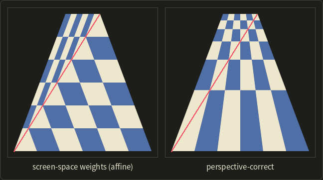
On the left, each triangle is textured as if it were flat on the screen: the rows don't get smaller with distance, and since the two triangles distort differently, the lines bend at the diagonal, the famous wobble of the first PlayStation.
On the right, the rows shrink towards the back and every line of the texture stays straight, as straight lines must under a projective map.
GPUs interpolate every varying perspective-correctly by default, but shading languages let you choose.
noperspective interpolates linearly on the screen (useful for screen-space quantities, such as the distance to a triangle's edges for wireframe drawing), and flat in GLSL or nointerpolation in Slang and HLSL passes one vertex's value unchanged (integers such as material IDs must be flat):
struct VSOutput {
  float4 position : SV_Position;
  float2 uv : TEXCOORD0;                       // perspective-correct (the default)
  noperspective float2 screenUV : TEXCOORD1;   // linear on the screen
  nointerpolation uint materialId : TEXCOORD2; // one vertex's value, not interpolated
};layout(location = 0) out vec2 uv; // perspective-correct (the default)
layout(location = 1) noperspective out vec2 screenUV; // linear on the screen
layout(location = 2) flat out uint materialId; // one vertex's value, not interpolatedstruct VSOutput {
float4 position : SV_Position;
float2 uv : TEXCOORD0; // perspective-correct (the default)
noperspective float2 screenUV : TEXCOORD1; // linear on the screen
nointerpolation uint materialId : TEXCOORD2; // one vertex's value, not interpolated
};Derivatives and 2×2 quads
Section 11.7 of chapter 11 chose the mipmap level from the derivatives of the texture coordinates, and so on, and mentioned that GPUs get them by comparing neighboring pixels.
Here's the mechanism.
The rasterizer never shades a single pixel: it emits fragments in 2 × 2 quads, and the four fragment shader invocations of a quad run together.
ddx(v) (Slang, HLSL) or dFdx(v) (GLSL) is simply the difference of between the right and the left pixel of the quad, ddy/dFdy between the two rows.
If a quad is only partly covered by the triangle, the uncovered pixels still run the shader as helper invocations, whose results are thrown away but whose values feed the differences.
Worked example. A floor (the camera is 1 m above it), a 90° vertical field of view on an 800 × 600 screen (aspect 4/3), and a texture with 100 texels per meter.
A pixel row (counted from the top) has , the floor point under it is at distance , and its texture coordinates in texels are and (section 19.2 run backwards).
For the quad of pixels 400 and 401 in rows 330 and 331:
| Pixel | (m) | (texels) | (texels) |
|---|---|---|---|
| (400, 330) | 9.836 | 1.639 | 983.61 |
| (401, 330) | 9.836 | 4.918 | 983.61 |
| (400, 331) | 9.524 | 1.587 | 952.38 |
| (401, 331) | 9.524 | 4.762 | 952.38 |
So and texels per pixel.
With the formula of chapter 11, and : almost exactly mip level 5.
The footprint is about times longer than wide, so anisotropic filtering would instead take about 10 samples (16× anisotropic allows it) from level .
These are the same numbers the polygon offset example used: one pixel row covers m of floor here.
Two consequences are worth knowing.
Small triangles are expensive: a one-pixel triangle still costs a quad of four invocations, three of them helpers (25% efficiency), one reason for level of detail and for the software rasterization of tiny triangles in some GPU-driven renderers (chapter 29).
And derivatives need all four invocations, so a texture lookup with automatic level selection doesn't belong inside a branch that only some pixels of a quad take.
Early-Z and hierarchical Z
Early-Z runs the test before the shader whenever the result can't change: the shader doesn't write its own depth, doesn't discard fragments and has no other side effects (or the program promises it doesn't matter, with layout(early_fragment_tests) in GLSL or [earlydepthstencil] in Slang/HLSL).
That's why a fragment-shader depth write, like the per-fragment logarithmic depth of section 19.4, has a real performance cost.
Hierarchical Z (Greene, Kass and Miller, 1993) rejects whole tiles at once.
Alongside the depth buffer, the GPU keeps for each tile the farthest depth stored in it (the maximum with standard Z).
Before rasterizing a triangle's pixels in a tile, it compares the triangle's nearest depth over the tile, which is the minimum of its depth plane at the tile's corners, with that value.
Worked example. An 8 × 8 tile has its farthest stored depth 0.6; a triangle's depth plane gives 0.70, 0.71, 0.72 and 0.73 at the tile's corners.
Its nearest point in the tile, 0.70, is behind everything already there, so all 64 fragments fail the depth test, and one comparison rejects them all.
With reversed Z, "farthest" is the minimum and the comparison flips.
Drawing the scene roughly front to back, or with a depth pre-pass (chapter 10), is what makes both early tests effective.
Exam points
This chapter goes beyond the syllabus, but it explains several syllabus items of area 2 (投影, ビューイングパイプライン, 描画パイプライン) and area 4 (隠面消去, マッピング):
- The perspective projection's stored depth is not linear in the distance: it follows , so precision is concentrated near the near plane (chapter 5, chapter 10). Moving the near plane outwards helps the most.
- The depth after projection is linear on the screen, which is why the Z-buffer method can interpolate it with screen-space (barycentric) weights.
- Clipping happens in homogeneous clip coordinates, before the perspective division, because points behind the eye have (chapter 6).
- Texture coordinates and other attributes need perspective-correct interpolation: interpolate and , then divide (chapter 6, chapter 11).
- The mipmap level is chosen from the screen-space derivatives of the texture coordinates (chapter 11).
- Shadow acne and z-fighting of coplanar surfaces are fixed with a depth bias that has a slope-scaled part (chapter 11).
19.6 Summary
- The perspective matrix puts the distance into ; its x and y rows map the frustum's near-plane rectangle to ±1 (off-center frusta add z terms); its z row can only be , so depth is always affine in .
- One formula covers OpenGL (−1 to 1), Vulkan/Direct3D (0 to 1) and reversed Z (1 to 0); letting gives infinite projections, and the reversed infinite one stores exactly .
- The inverse projection recovers camera positions from depth: then a division by , or the distance times the pixel's ray.
- Clipping is done in clip space before the division; new vertices get attributes by linear interpolation in clip space, which is exact; GPUs avoid side clipping with guard bands and can clamp depth instead of clipping near and far.
- Fixed-point depth has a uniform step, float depth a uniform relative step; standard Z wastes the float's precision, reversed Z with a float buffer gives a distance step of about to of the distance everywhere.
- Logarithmic depth also gives relative precision but breaks screen-space linearity or early-Z; depth bias separates coplanar surfaces and fights shadow acne.
- Edge functions are linear and evaluated incrementally; the top-left rule gives every pixel on a shared edge to exactly one triangle; integer arithmetic after snapping to a sub-pixel grid makes this exact.
- Tiles allow trivial rejection and acceptance of many pixels at once; barycentric coordinates make every attribute a plane over the triangle.
- is linear on the screen; attributes are divided by ; depth needs no correction.
- Fragments are shaded in 2 × 2 quads to provide derivatives for mipmapping; early-Z and hierarchical Z reject hidden fragments before shading.
19.7 Key terms
| English | 日本語 |
|---|---|
| projection matrix | 投影行列 |
| off-center (asymmetric) frustum | 非対称な視錐台 |
| depth range, depth convention | 深度範囲 |
| reversed Z | リバースZ |
| infinite far plane | 無限遠のファー平面 |
| inverse projection | 逆投影 |
| depth reconstruction | 深度からの位置の復元 |
| clip coordinates | クリップ座標系 |
| homogeneous clipping | 同次座標でのクリッピング |
| near-plane clipping | ニア平面でのクリッピング |
| guard band | ガードバンド |
| depth clamping | 深度クランプ |
| depth precision | 深度精度 |
| fixed-point (UNORM) depth format | 固定小数点(UNORM)の深度フォーマット |
| floating-point depth format | 浮動小数点の深度フォーマット |
| logarithmic depth | 対数深度 |
| z-fighting | Zファイティング |
| depth bias, polygon offset | デプスバイアス、ポリゴンオフセット |
| slope-scaled depth bias | スロープスケールのデプスバイアス |
| decal | デカール |
| edge function | エッジ関数 |
| incremental evaluation | インクリメンタルな評価 |
| top-left rule | トップレフトルール |
| sub-pixel precision | サブピクセル精度 |
| fixed-point snapping | 固定小数点へのスナップ |
| bounding box traversal | バウンディングボックスの走査 |
| tiled traversal | タイル単位の走査 |
| trivial reject, trivial accept | 自明な棄却、自明な受理 |
| barycentric coordinates | 重心座標 |
| perspective-correct interpolation | パースペクティブコレクト補間 |
| helper invocation | ヘルパー起動(ヘルパーインボケーション) |
| 2×2 quad | 2×2クアッド |
| screen-space derivatives | スクリーン空間の微分 |
| early-Z | アーリーZ |
| hierarchical Z | 階層Z(Hi-Z) |
19.8 Challenges
- ★ With the general z-row formula of section 19.1, compute and for and in the OpenGL, Vulkan and reversed conventions, and the stored 0 to 1 depth of a point at distance 2 in each. (Check: the reversed value is one minus the Vulkan value, and the OpenGL value converted with equals the Vulkan one.)
- ★ A Vulkan renderer uses
perspectiveVkwith 90°, aspect 4/3, and on an 800 × 600 window (y down). The depth buffer holds 0.9 at the window position . Reconstruct the camera-space position with the shortcut of section 19.2, then project it again to check. - ★★ Clip the triangle with camera positions , , against the near plane, using the OpenGL matrix of section 19.3 (, ). How many vertices does the result have, and where are the new ones in camera space and in NDC?
- ★★ For m and m, estimate the distance step at 50 m and at 400 m for a 24-bit UNORM buffer with standard Z and for a float32 buffer with reversed Z. By what factor does moving the near plane to 0.05 m change each of the two?
- ★★ An edge goes from a vertex with , to a vertex with , . What is at the screen midpoint, and at which fraction of the screen distance is ? Sketch against the screen position.
- ★★★ Four triangles share the vertex , which is a pixel center, and form a fan inside the square from to (one triangle per side of the square). Show with the top-left rule (y up, counter-clockwise) that exactly one of the four triangles covers the center , find which one, and count all pixels of the square. Why is the top-left rule, applied edge by edge, enough to handle shared vertices as well?
Multiple choice
Q1 ★ Which of the following statements about clipping in the viewing pipeline is correct?
| A | Clipping is done after the perspective division, because the view volume is then a simple cube. |
| B | A vertex behind the camera has a positive w in clip coordinates, so it passes the clip test. |
| C | In OpenGL's convention the near-plane test is . |
| D | A new vertex created on the near plane gets its attributes by linear interpolation in clip space, which is correct because clip coordinates are a linear function of camera coordinates. |
| E | With a guard band, the GPU never needs to clip against the near plane. |
Q2 ★★ A perspective projection with a near plane of 0.1 m and a far plane of 1000 m is used. Which of the following statements about depth precision is correct?
| A | With a 32-bit floating-point depth buffer and reversed Z (near at 1, far at 0), the distance covered by one step of the stored depth is roughly proportional to the distance. |
| B | With the standard mapping (near at 0, far at 1), a 32-bit float buffer is about a thousand times more precise far away than a 24-bit fixed-point buffer. |
| C | Moving the near plane closer to the camera, from 0.1 m to 0.01 m, makes the 24-bit fixed-point buffer more precise far away. |
| D | Reversed Z works just as well with OpenGL's default depth range from −1 to 1. |
| E | With a 24-bit fixed-point buffer, the distance covered by one step is the same at every distance. |
Q3 ★★ An edge of a triangle goes from a vertex with and texture coordinate to a vertex with and . What is the perspective-correct value of at the midpoint of the edge on the screen?
| A | 0.5 |
| B | 0.2 |
| C | 0.8 |
| D | 0.625 |
| E | 0.4 |
19.9 Practical assignment
Take one triangle through clipping, rasterization, perspective-correct interpolation and depth reconstruction, all by hand, using the reversed infinite projection.
You need graph paper with a 16 × 16 grid (1 cm per pixel is comfortable), a ruler, a pencil, two colored pens and a calculator.
The projection is the reversed infinite matrix of section 19.1 with a 90° field of view, aspect ratio 1 and , used with OpenGL's y-up window but a 0 to 1 depth range (what glClipControl(GL_LOWER_LEFT, GL_ZERO_TO_ONE) sets up).
Its rows are , , and , so and .
The clip test is and .
The window is 16 × 16 pixels with the origin at the bottom-left: , , and the stored depth is .
The triangle has the camera-space vertices , and , with a texture coordinate , , .
- Project. Compute the clip coordinates of A, B and C and apply the clip test. Which vertex fails, which plane does it fail, and why couldn't you divide it by its anyway?
- Clip. The signed value for the near plane is . Find the points on AC and on BC where , with their clip coordinates and their . Write the clipped polygon in order A, B, , .
- To the window. Divide and apply the viewport to the four vertices; write down each one's window position and stored depth. Draw the quadrilateral on the graph paper and split it along into and .
- Rasterize. Color every pixel whose center lies in with the first pen and in with the second, using edge functions where a center is close to an edge and the top-left rule if one lies exactly on an edge. Count the pixels and compare with the quadrilateral's area from the shoelace formula.
- Interpolate. For the pixel with center , compute the edge functions of and its screen weights . Then compute naively and perspective-correctly, the interpolated and the interpolated stored depth.
- Reconstruct. From the pixel's NDC position and its stored depth, compute its camera-space position (section 19.2: here the distance is ). Find the 3D weights and compute from them.
How to check yourself:
- Step 2: both new points have camera , and lies exactly halfway between A and C.
- Step 3: all four window positions are whole numbers inside the grid; the depths of and are 1 (they're on the near plane), and every depth equals .
- Step 4: the number of colored pixels is within a few pixels of the area (95 pixels), and no pixel has both colors.
- Step 5: the three add up to 1; the interpolated depth equals the interpolated exactly, because with this projection the depth is .
- Step 6: the reconstructed point satisfies the plane equation of the triangle ABC; the add up to 1, and equals your perspective-correct from step 5, not the naive one.
コメント(0)
まだコメントはありません。
ログインするとコメント出来ます。