5. 3D Transformations and Projection
In chapter 4 we moved, turned and stretched shapes in a flat 2D world.
Now we step up to 3D, where our virtual camera from chapter 2 actually lives, and then we answer the question every CG image has to answer at the end: how does a 3D scene become a flat picture?
That second step is called projection (投影, tōei).
This chapter covers two items of syllabus area 2 (座標変換とパイプライン): 3D transformations (3次元変換) and projection (投影).
The matrices themselves were derived in the Linear Algebra series, chapters 8 to 13, so I won't derive everything again.
Instead, I'll recap each tool quickly, link to where it was built, and spend the time on the CG view and the exam view: the conventions, the classifications, what each transform or projection keeps and what it destroys, and lots of worked numbers.
Here's the plan:
- 3D coordinate systems: right-handed and left-handed, and the spaces a vertex travels through.
- The basic 3D transforms as 4×4 matrices, rotation about any axis, and Euler angles.
- Why normal vectors need a different matrix.
- The view transform built from an eye, a target and an up direction.
- The family tree of projections: parallel (orthographic, axonometric, oblique) and perspective (one-, two- and three-point).
- Perspective in formulas: similar triangles, the 4×4 projection matrix, perspective division and the view frustum.
Chapter 6 then strings all of this together into the full viewing pipeline, with clipping and the viewport.
5.1 3D coordinate systems
Right-handed and left-handed
In 2D there was only one sensible choice: x to the right, y up.
In 3D, once x and y are fixed, z can point either towards you or away from you, and that gives two different kinds of coordinate system:
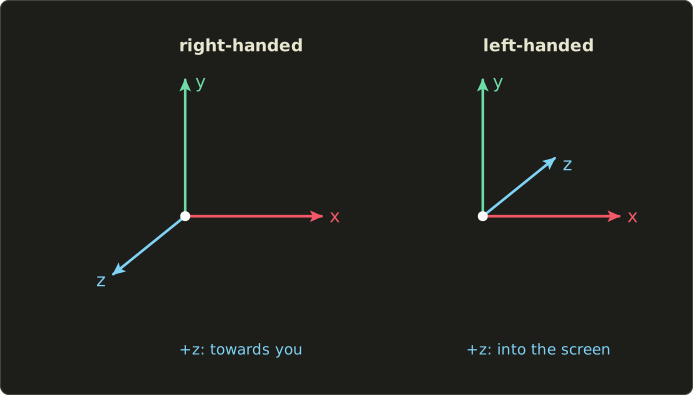
- A right-handed system (右手系, migite-kei): point the fingers of your right hand along +x, curl them towards +y, and your thumb points along +z. With x right and y up, +z comes out of the screen towards you. This series, OpenGL-style math, Blender and Maya use it.
- A left-handed system (左手系, hidarite-kei): the same with your left hand, so +z goes into the screen. Unity, Unreal Engine (with z up) and the traditional Direct3D convention use it.
Neither one is "correct"; they are conventions.
Chapter 1 already showed how to convert: flip z with , and a transform becomes .
Here is one consequence that's worth seeing with numbers.
Take the rotation about y and work out .
Multiplying by on the left negates the third row, and on the right negates the third column, so the entry in the corner (row 3, column 3) is negated twice and stays the same:
The same happens for x: .
But , because has nothing in its third row or column except the 1.
So when you move a scene from a right-handed tool to a left-handed engine, z positions change sign, rotation angles about x and y (the axes that lie in the mirror plane) change sign, and the angle about z doesn't.
The matrices are written the same way in both systems; what changes is what "positive" looks like.
In a right-handed system a positive rotation follows the right-hand rule (thumb along the axis, fingers curl the way it turns), and in a left-handed system the left-hand rule.
Seen from the positive end of the axis looking back at the origin, that's counter-clockwise in a right-handed system and clockwise in a left-handed one.
Local, world and camera spaces
Just like in 2D (chapter 4), a 3D scene uses several coordinate systems at once:
- Local coordinates (ローカル座標系, also モデリング座標系 or 物体座標系): the coordinates a model was built in, usually with the origin at the model's center or its feet.
- World coordinates (ワールド座標系): the one shared space where all objects, lights and the camera are placed.
- Camera coordinates (カメラ座標系, also 視点座標系 or view space): the world as seen from the camera, with the camera at the origin looking down −z.
The modeling transform (モデリング変換) takes local to world, and the view transform (ビュー変換, also 視野変換) takes world to camera.
After that comes projection, which this chapter ends with, and then clipping and the screen, which are chapter 6.
The Linear Algebra series followed one vertex on this journey in chapter 11.
5.2 The basic 3D transforms
The 4×4 homogeneous matrices
In 3D we use homogeneous coordinates (同次座標, dōji zahyō) with four numbers: a point is and a direction is .
The extra coordinate lets translation be a matrix too, exactly like the 3×3 matrices of chapter 4 did in 2D (Linear Algebra chapter 9).
Here are the five basic transforms:
Each rotation about a coordinate axis is the 2D rotation of chapter 4 applied to the other two coordinates, with the axis's own coordinate left alone.
The one to watch is : its minus sign sits in the bottom-left, not the top-right.
The reason is the cycle x → y → z → x: about z, x turns towards y; about x, y turns towards z; and about y, z turns towards x.
Linear Algebra chapter 8 checks every sign with the right-hand rule, so I'll just give one quick test you can do in your head: must send +z (towards you) to +x (right), because seen from above, a counter-clockwise quarter turn takes the front of an object to its right side.
The third column of is . It does.
There are two more basic linear transforms in 3D, the same ideas as in 2D:
- Reflection (鏡映, kyōei) negates one coordinate, for example mirrors in the xy plane. Its determinant is −1, so it turns the object "inside out" and reverses the vertex order of its triangles.
- Shear (せん断, sendan) adds a multiple of one coordinate to another, for example . In 3D there are six such pairs.
All of these are affine transformations (アフィン変換), so everything chapter 4 said about affine maps still holds: straight lines stay straight, parallel lines stay parallel, and ratios along a line are kept.
Rotations and translations together are the rigid transformations (剛体変換): they keep lengths and angles.
Order matters: a worked example
Matrix products don't commute, in 3D just as in 2D.
Take the point and two transforms: and .
With and , maps to .
Rotate first, then translate (, read right to left):
Translate first, then rotate ():
Different results.
In the second order the rotation also swings the translation around, because it rotates about the world origin, not about the object.
That's why the usual model matrix is : scale first, then rotate, both while the object still sits at the origin, and move it into place last.
Inverses
The inverses work exactly as in 2D (section 4.3): , , (and the same for y and z), a reflection is its own inverse, and a product is undone in reverse order, .
The inverse of a rotation is its transpose, because its columns are perpendicular unit vectors (Linear Algebra chapter 10).
We'll use that twice in this chapter: for normals and for the view transform.
5.3 Rotation about an arbitrary axis
An axis through a point: the door hinge
A door doesn't turn about the world's y axis; it turns about its hinge.
The trick is the same as rotating about a point in chapter 4: move the axis to the origin, rotate, and move it back.
For an axis parallel to y through the point :
Let's open a door by 90°.
The hinge passes through , and the door's edge is at .
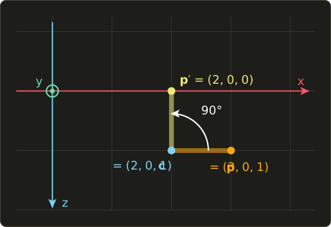
Step by step:
- : . The hinge is now at the origin.
- maps to , so .
- : .
So : the edge swung from the right side of the hinge to the back of it, a counter-clockwise quarter turn seen from above.
Multiplying the three matrices gives one matrix for the whole door:
Check it with the hinge itself: .
Points on the axis don't move, as they shouldn't.
An axis in any direction: the composite method
When the axis direction is slanted, a classic approach builds the rotation from basic ones.
Say the axis goes through with unit direction , and let :
- moves the axis to the origin.
- with , turns into the xz plane: it becomes .
- with , turns it onto the z axis: it becomes .
- does the actual rotation.
- Undo steps 3, 2 and 1 in reverse order.
(If , the axis already lies along x and you can use directly.)
It's long, but every piece is something we already know, and the pattern "move the problem to where it's easy, solve it, move it back" shows up all over CG.
An axis in any direction: Rodrigues' formula
The direct way is Rodrigues' rotation formula (ロドリゲスの回転公式), derived in Linear Algebra chapter 13.
For a unit axis through the origin and an angle :
In words: the part of along the axis stays put, and the part perpendicular to it turns in its plane like a 2D rotation, with playing the role of the second axis.
Let's rotate by 90° about .
First check that is a unit vector: . Good.
With , , the first term disappears and .
Two checks that should always pass for a rotation:
- The length is kept: and .
- The component along the axis is kept: , the same as before.
As a matrix, , where is the cross product matrix of .
For our axis and angle that's :
and , the same answer.
For an axis that doesn't pass through the origin, wrap it in like the door.
Euler angles and gimbal lock
The most human way to describe an orientation is three angles, one per axis: Euler angles (オイラー角).
For cameras and vehicles they're called yaw (about the up axis), pitch (about the side axis) and roll (about the forward axis).
They are great as input, for example the three rotation fields in a 3D tool, but they have three problems:
- The order matters. and are different orientations, and different programs choose different orders, so three numbers mean nothing until you also know the order.
- Fixed or moving axes. The same product can be read two ways. Read right to left, rotates about the fixed world axes z, then x, then y. Read left to right, it rotates about the object's own axes: first its y, then its new x, then its new z. Both readings give the same matrix.
- Gimbal lock (ジンバルロック). When the middle rotation reaches 90°, the first and last axes line up and turn about the same line. One degree of freedom is lost, and near that pose small changes of orientation need huge jumps in the angles.
Linear Algebra chapter 13 shows gimbal lock with numbers and introduces the cure, quaternions (クォータニオン, 四元数), which store an orientation without gimbal lock and blend smoothly between two orientations with slerp.
We'll come back to them for animation in chapter 13.
5.4 Transforming normal vectors
A normal vector (法線ベクトル, hōsen bekutoru) points straight out of a surface, and lighting depends on it in every chapter from 10 onwards.
So when we transform a model, we must transform its normals too.
The obvious idea is to multiply them by the same matrix (with , since they are directions).
That works for rotations and uniform scaling, but with non-uniform scaling or shear the normals stop being perpendicular to the surface.
A worked 3D example
Take the triangle , , .
It lies in the plane , so its normal is (not normalized, which is fine for checking angles).
Now scale the model by :
The true normal of the new triangle is the cross product of two of its edges (Linear Algebra chapter 5):
The naive normal is .
Is it perpendicular to the edges?
No.
Now try the inverse transpose .
, and a diagonal matrix is its own transpose, so:
Exactly the true normal.
The picture shows both triangles seen exactly along one of their edges, so each triangle looks like a line segment and a correct normal meets it at a visible right angle:
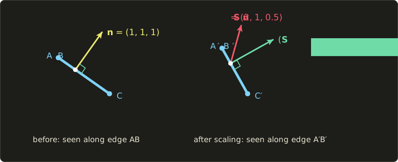
Stretching the triangle along x made it lean over, so its normal must lean less towards x, which is what dividing by 2 does.
The rule
For a model matrix whose upper-left 3×3 part is , transform normals with the normal matrix (法線行列):
and normalize the result afterwards, because doesn't keep lengths.
The reason in one line: a normal is defined by for every tangent of the surface, tangents transform with , and is zero for every such when .
The full derivation is in Linear Algebra chapter 10.
When you can skip it:
- Rotation only: , so the normal matrix is the model matrix itself.
- Rotation and uniform scale : the normal matrix is , which points the same way as , so after normalizing the plain matrix is fine.
- Translation never affects normals, since directions have .
In practice, engines compute the normal matrix once per object on the CPU and pass it to the vertex shader, which transforms positions and normals side by side:
struct Transformed {
  float4 clipPos;
  float3 worldNormal;
};

Transformed transformVertex(float4x4 model, float4x4 view, float4x4 proj,
                            float3x3 normalMatrix, float3 pos, float3 normal) {
  Transformed o;
  float4 world = mul(model, float4(pos, 1.0));
  o.clipPos = mul(proj, mul(view, world));
  o.worldNormal = normalize(mul(normalMatrix, normal));
  return o;
}
struct Transformed {
vec4 clipPos;
vec3 worldNormal;
};
Transformed transformVertex(mat4 model, mat4 view, mat4 proj,
mat3 normalMatrix, vec3 pos, vec3 normal) {
Transformed o;
vec4 world = model * vec4(pos, 1.0);
o.clipPos = proj * view * world;
o.worldNormal = normalize(normalMatrix * normal);
return o;
}struct Transformed {
float4 clipPos;
float3 worldNormal;
};
Transformed transformVertex(float4x4 model, float4x4 view, float4x4 proj,
float3x3 normalMatrix, float3 pos, float3 normal) {
Transformed o;
float4 world = mul(model, float4(pos, 1.0));
o.clipPos = mul(proj, mul(view, world));
o.worldNormal = normalize(mul(normalMatrix, normal));
return o;
}You'll write a complete version of this in the OpenGL series.
5.5 The view transform
Moving the world instead of the camera
The view transform takes world coordinates into camera coordinates, where the camera sits at the origin and looks down −z with +y up.
If the camera was placed in the world by a rigid transform (rotate it, then move it to the eye position ), the view matrix is the inverse:
It's the rule of section 4.3 in 3D: moving the coordinate system by is the same as moving the objects by .
Stepping the camera 1 m to the right looks exactly like sliding the whole world 1 m to the left.
Building the axes from eye, target and up
Nobody types a rotation matrix for a camera.
Instead we give three things: the eye position , a target point to look at, and a rough up direction (usually ).
From them we build the camera's three axes with cross products (Linear Algebra chapter 11 explains each step):
Forward points at the target, right is perpendicular to forward and to the up hint, and the true up is perpendicular to both.
The rows of are , and (minus, because the camera looks down −z), so:
This is the well-known lookAt function.
If the camera looks exactly along the up hint, is zero and the construction fails, so a camera looking straight down needs a different up hint.
A worked example: a camera looking down at a slant
The camera is at , looks at the origin, and the up hint is .
This camera is above and in front of the origin, looking down at it.
Forward. , its length is , so .
Right. With the cross product simplifies to :
The camera's right is the world's +x, as you'd expect for a camera that only tilts forward.
True up.
The camera's up leans forward, towards the target's side (its z is negative), because the camera is tilted down: nod your head and the top of it points forward too.
Translation column.
Assemble.
Check. The target (the origin) should end up straight ahead at distance 5: . Correct.
The eye should end up at the origin: . Correct.
And a corner of a unit cube, :
1 to the right, 0.2 above the center of view, 3.6 in front of the camera.
Exam points
- Composition reads right to left with column vectors: in the scale happens first. Books with row vectors write the transposed matrices in the opposite order (section 4.6).
- The minus sign of is in the bottom-left. Positive rotation follows the right-hand rule in a right-handed system.
- Rotation about an axis through a point : .
- Inverse of a rotation = its transpose; inverse of a product = product of the inverses in reverse order.
- Euler angles depend on the order and suffer from gimbal lock; quaternions don't.
- Normals transform with , then get normalized. With only rotation and uniform scale, the model matrix itself works.
- The view transform is the inverse of the camera's placement.
5.6 Projection: the big picture
Projection maps 3D points onto a 2D projection plane (投影面, tōeimen), the virtual film or screen.
Every point is carried to the plane along a line called a projector (投影線).
How the projectors are arranged decides the kind of projection:
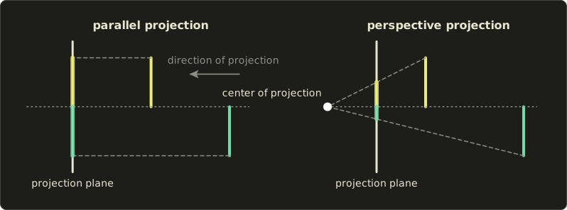
- In parallel projection (平行投影, heikō tōei) all projectors are parallel to one direction of projection (投影方向). The two objects in the picture have the same height, and so do their images, no matter how far away they are.
- In perspective projection (透視投影, tōshi tōei) all projectors pass through one point, the center of projection (投影中心), which is the eye or the pinhole of the camera from chapter 2. The farther object makes a smaller image.
You can think of parallel projection as perspective projection with the center of projection moved infinitely far away: the projectors then become parallel.
Both families split further.
Here's the whole family tree, which is worth knowing by heart for the exam:
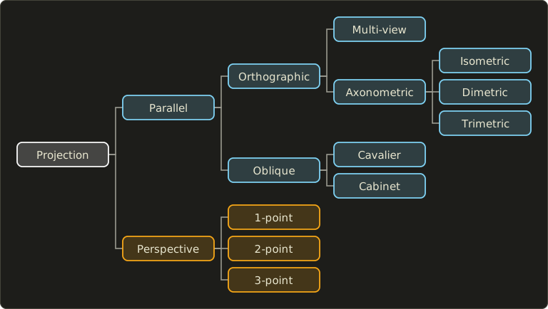
The next two sections walk through the tree, left branch first.
5.7 Parallel projection
Orthographic projection and multi-view drawings
If the projectors are perpendicular to the projection plane, the parallel projection is an orthographic projection (正投影, seitōei).
The simplest one projects onto the xy plane by forgetting z:
Its determinant is 0: it squashes space flat and can't be undone, because every point on a projector lands on the same spot.
(GPU projection matrices keep a depth value for the depth buffer, so they are invertible; see Linear Algebra chapter 12 and section 5.9.)
When the plane is parallel to one face of the object, that face is shown in its true shape and size, which is what engineers need.
So technical drawings use several such views, a multi-view projection (多面投影): the front view (正面図), the top view (平面図) and a side view (側面図), together called a three-view drawing (三面図, sanmenzu).
Here is an L-shaped block, with the views arranged the way JIS and American drawings do it (third-angle projection, 第三角法: the top view above the front view, the right side view to its right):
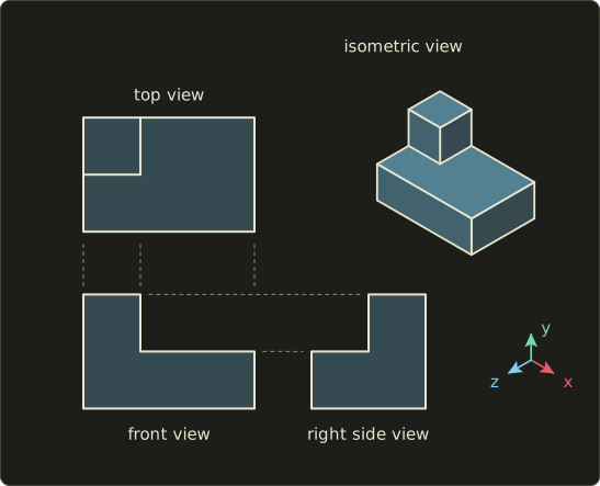
Each view is just after a rotation that turns the chosen side towards the viewer, and the views share their measurements: the width in the front view equals the width in the top view, and the height equals the height in the side view (the dashed lines).
The weakness is that no single view shows the object in 3D; you need to read them together.
Axonometric projection: isometric, dimetric, trimetric
If we turn the object (or the plane) so that none of its main faces is parallel to the projection plane, one orthographic view shows three faces at once.
That is axonometric projection (軸測投影, jikusoku tōei).
Every axis of the object then appears shorter than it really is, by a foreshortening factor (短縮率).
For an orthographic projection along the unit direction , the x axis is shortened to of its length, and the same for y and z (the part of the axis along is lost).
Axonometric projections are named after how many of the three factors are equal:
- Isometric (等角投影, tōkaku tōei, also アイソメトリック): all three equal.
- Dimetric (二等角投影, also ダイメトリック): two equal.
- Trimetric (不等角投影, also トリメトリック): all three different.
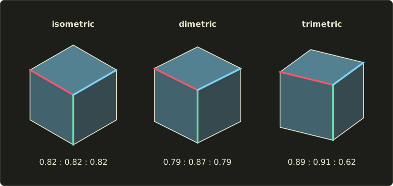
Worked example: isometric with lookAt.
Isometric means looking along the cube's diagonal, .
So each factor is .
We can get the actual drawing from the camera of section 5.5: put the eye at , look at the origin, up hint , and drop the depth.
Then , , and after normalizing and one more cross product:
A point lands on the drawing at .
The three unit axes land at:
All three have length , and they point at −30°, 90° and −150°, so they're 120° apart.
That's the familiar isometric look: vertical lines stay vertical, and the other two axes run at 30° to the horizontal, one to each side.
Drafters usually skip the 0.816 and draw all three axes at full length; that is called an isometric drawing (等角図), and it is simply the isometric projection scaled up by .
A nice check: since , the squares of the three factors always add up to .
For isometric, ; for the dimetric cube above, .
In practice.
CAD programs offer isometric, dimetric and trimetric preset views, and strategy and puzzle games love the look.
Most "isometric" pixel-art games actually use a dimetric projection: their floor lines rise 1 pixel for every 2 pixels across, an angle of instead of 30°, because 2:1 steps make clean pixel lines.
That corresponds to looking down at 30° from the horizontal, which gives factors of about 0.79 for the two floor axes and 0.87 for the vertical one, exactly the dimetric cube above.
Oblique projection: cavalier and cabinet
In an oblique projection (斜投影, shatōei) the projectors are parallel but not perpendicular to the projection plane.
The front face, parallel to the plane, keeps its true shape, like in a front view, but the depth axis is drawn as a slanted line at an angle , scaled by a factor .
With the depth direction being −z in our coordinates, a point one unit behind the front face moves by in the direction :
The two named kinds differ only in :
- Cavalier projection (カバリエ投影): . The depth is drawn at full length, and cubes look too deep. The projectors meet the plane at 45°.
- Cabinet projection (キャビネット投影): . Depth is drawn at half length, which looks much more natural. The projectors meet the plane at .
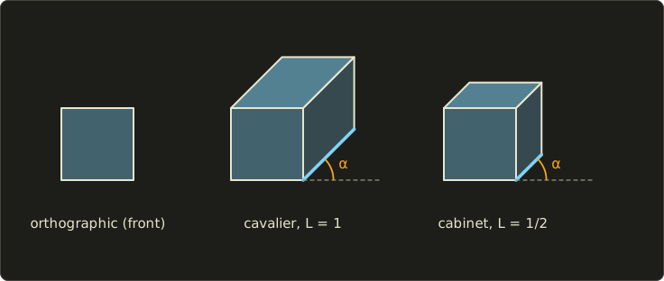
The angle is usually 45° or 30°.
As a matrix, oblique projection is a shear followed by dropping z:
Worked example. Cabinet projection with , so .
The point , two units behind the front:
With cavalier () it would land at : its offset from is twice as long.
Oblique projections are easy to draw by hand on graph paper, which is why textbooks, furniture catalogs and the background of many 2D games use them.
What every parallel projection keeps
All parallel projections are affine maps (a rotation or shear, then dropping z), so they keep what affine maps keep:
- Straight lines stay straight, and parallel lines stay parallel.
- Ratios along a line are kept: the midpoint of an edge is drawn at the midpoint of the drawn edge.
- The size of an object does not depend on its distance.
- Faces parallel to the projection plane keep their true shape (orthographic and oblique).
What they lose is the depth cue of perspective: you can't tell from the picture how far away something is.
5.8 Perspective projection
Foreshortening and the center of projection
Perspective projection is what an eye or a pinhole camera does.
Things farther away are drawn smaller, and lines that run away from you look shorter than they are, an effect called foreshortening (短縮, also フォアショートニング).
It's the strongest depth cue in a single picture, which is why almost all 3D games and films use it.
Vanishing points
The most striking feature of perspective is that parallel lines can meet.
Railway tracks run parallel forever, but in a photo they converge to a point on the horizon.
That point is a vanishing point (消失点, shōshitten).
Here's where it comes from.
Put the center of projection at the origin, looking down −z, with the projection plane at distance (section 5.9 explains why the projection is ).
A line through the point with direction is .
Project it and let grow without end:
The starting point disappeared!
Every line with the same direction heads for the same image point, which depends only on the direction.
And if , that is, if the lines are parallel to the projection plane, there's no vanishing point: those lines stay parallel in the picture.
In short:
- Every direction that is not parallel to the projection plane has one vanishing point.
- Directions parallel to the projection plane have none; such lines stay parallel.
- All horizontal directions vanish on one line, the horizon (水平線), at the height of the eye.
One-, two- and three-point perspective
A box has three edge directions.
How many of them are parallel to the projection plane decides how many vanishing points the box shows:
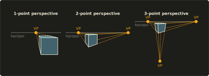
- One-point perspective (1点透視): the box faces the camera squarely. Its widths and heights are parallel to the plane and stay parallel; only the depth edges converge, to a single vanishing point straight ahead. Corridors and roads seen head-on look like this.
- Two-point perspective (2点透視): the box is turned about the vertical axis, and the camera is level. The two horizontal edge directions vanish at two points on the horizon, and the vertical edges stay vertical. Architectural renderings use this a lot, because buildings look upright.
- Three-point perspective (3点透視): the camera also tilts up or down. Now no edge direction is parallel to the plane, and the vertical edges converge too, to a third point far below (or above). Looking up at a skyscraper gives this dramatic look.
All three pictures above are real projections of the same box, computed with the formula for and , not drawn by eye.
A worked example: two vanishing points
Take and a box turned by about the vertical axis, with a level camera.
Its two horizontal edge directions are and (each pointing away from the camera; they're perpendicular, since ).
Both have , so both lie on the horizon at eye height.
The vertical direction has , so it has no vanishing point and vertical edges stay vertical: two-point perspective.
There's a pretty pattern here.
In general the two points are at and , so their product is always
When you turn the box, one vanishing point slides towards the center and the other runs off to the side, but the product stays the same.
You'll use this as a self-check in the practical assignment.
What perspective keeps and what it doesn't
- Straight lines stay straight.
- Parallel lines don't stay parallel unless they are parallel to the projection plane.
- Ratios along a line are not kept: the middle of a long wall going into the distance is drawn closer to the far end than the near end, which is why perspective-correct texture interpolation is needed (chapter 6 and Part 2).
- Size falls off as .
In chapter 4 terms, perspective projection is a projective transformation (射影変換), not an affine one.
5.9 Perspective projection in formulas
Similar triangles
Look at the camera from the side.
The center of projection is at the origin, the projection plane is at distance , and a point is in front of the camera at distance (remember, the camera looks down −z, so z is negative in front of it).
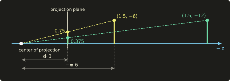
The small triangle (eye, plane, image) and the big triangle (eye, point) have the same angles, so their sides are in proportion:
Perspective is a division by the distance.
In the picture, and both points have height (the labels give ):
Twice as far, half as tall.
Some books use a camera that looks down +z instead, and then the formula reads ; it's the same idea with the sign of z flipped.
As a 4×4 matrix: perspective division
A matrix can only multiply and add, it can't divide by z.
Homogeneous coordinates solve this: a 4D vector with any stands for the 3D point .
So we let the matrix put the distance into , and divide afterwards:
Dividing by gives : exactly the similar-triangle formulas, and every point lands on the plane .
This division is called perspective division (透視除算, tōshi jozan), and it's the step that makes a projection projective rather than affine.
On a GPU it happens automatically after the vertex shader.
Worked example. and the point :
The image is at on the plane , matching and from before.
Notice that the result's z is always : this matrix throws depth away (its third and fourth rows are multiples of each other, so its determinant is 0), and with it the information about which surface is in front.
That's why real renderers use a slightly different matrix.
The view volume and the frustum
A real camera doesn't see everything.
It sees a limited angle, the field of view (視野角, shiyakaku) , and the image has an aspect ratio = width / height.
Renderers also choose a near plane (ニア平面, also 前方クリップ面) at distance and a far plane (ファー平面, also 後方クリップ面) at distance ; anything closer or farther is clipped away.
The region that can appear in the image is the view volume (視体積, shitaiseki).
For perspective it's a pyramid with its tip cut off, the frustum (視錐台, shisuidai); for orthographic projection it's a box.
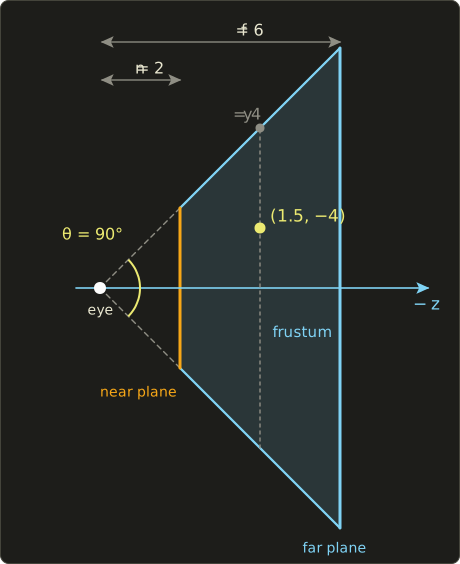
The GPU's perspective matrix maps the frustum onto a cube, the normalized device coordinates (NDC, 正規化デバイス座標), which go from −1 to 1 in OpenGL.
With , the OpenGL version is:
Compared with , the x and y rows scale by the field of view (so the edges of the frustum land on ±1), and the z row keeps a depth value instead of throwing it away, mapping the near plane to −1 and the far plane to +1.
The bottom row still copies into for the perspective division.
Linear Algebra chapter 12 derives every entry and gives the Vulkan version (y flipped, depth from 0 to 1).
Worked example. Field of view 90°, aspect ratio 4:3, , :
Take the camera-space point :
Perspective division by :
Look at the frustum picture to see why : with a 90° field of view, the frustum at distance 4 reaches from to , and of the way up is exactly where the point is.
The step that turns NDC into pixel positions is the viewport transform, in chapter 6.
Depth is not linear
Look at the depth of that example.
The point at distance 4 is exactly halfway between the near plane (2) and the far plane (6), but its NDC z is 0.5, not the middle of −1 to 1.
After division, the depth is , which follows , not the distance itself.
With our numbers, the middle of the range (NDC z = 0) is at distance , not 4.
The plot shows the same thing for , , with the depth stored in a 0 to 1 depth buffer:
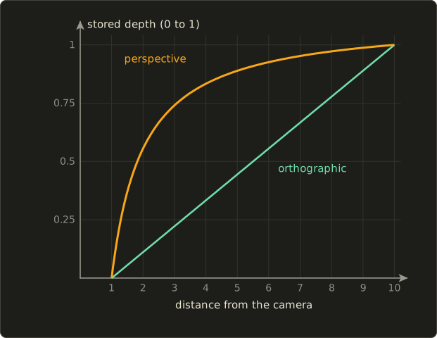
Perspective spends most of its depth precision close to the camera, and far surfaces share very little of it.
With limited bits, two far surfaces can get the same stored depth and flicker through each other (z-fighting).
The practical rule: put the near plane as far out as you can.
Orthographic depth is linear, the straight line.
The depth buffer itself is chapter 10, and Part 2 goes deeper into depth precision.
Exam points
- Parallel vs perspective: parallel projectors (center of projection at infinity) vs projectors through one center of projection.
- Orthographic: projectors perpendicular to the plane. Oblique: parallel but slanted. Cavalier keeps the depth at full length, cabinet at half.
- Axonometric names count equal foreshortening factors: isometric (3 equal, axes 120° apart, factor ), dimetric (2), trimetric (none).
- Parallel projection keeps parallel lines and ratios along lines; perspective keeps straight lines but not parallelism or ratios, and image size falls with distance.
- A box in perspective has as many vanishing points as edge directions that are not parallel to the projection plane: 1, 2 or 3. Lines parallel to the plane have no vanishing point.
- comes from similar triangles; in matrix form the division is the perspective division by .
- The view volume of perspective is a frustum (near plane, far plane, field of view, aspect ratio); the stored depth is not linear in distance.
- The order of the whole chain is : model, then view, then projection.
5.10 Code
Here is the whole chain in C++ with the Linear Algebra series' header linalg.hh: Rodrigues' rotation as the model matrix, the camera of section 5.5, and the projection of section 5.9.
The second part checks the normal example of section 5.4.
#include <cstdio>
#include <numbers>
#include "linalg.hh"

int main() {
  const float pi = std::numbers::pi_v<float>;

  // 1. model: 90° about the axis (0, 0.6, 0.8)
  Mat4 model = rotate({0.0f, 0.6f, 0.8f}, pi / 2.0f);
  // 2. view: eye (0, 3, 4) looking at the origin
  Mat4 view = lookAt({0.0f, 3.0f, 4.0f}, {0.0f, 0.0f, 0.0f}, {0.0f, 1.0f, 0.0f});
  // 3. projection: 90° vertical fov, aspect 4:3, near 2, far 6
  Mat4 proj = perspectiveGl(pi / 2.0f, 4.0f / 3.0f, 2.0f, 6.0f);

  Vec4 p{1.0f, 2.0f, 0.0f, 1.0f};
  Vec4 world = model * p;
  Vec4 eye = view * world;
  Vec4 clip = proj * eye;
  Vec4 ndc = (1.0f / clip.w) * clip; // perspective division

  printf("world (%.4f, %.4f, %.4f)\n", world.x, world.y, world.z);
  printf("view  (%.4f, %.4f, %.4f)\n", eye.x, eye.y, eye.z);
  printf("clip  (%.4f, %.4f, %.4f, %.4f)\n", clip.x, clip.y, clip.z, clip.w);
  printf("ndc   (%.4f, %.4f, %.4f)\n", ndc.x, ndc.y, ndc.z);

  // normal of the triangle x + y + z = 1 after scale(2, 1, 0.5)
  Mat4 s = scale({2.0f, 1.0f, 0.5f});
  Mat4 normalMatrix = transpose(inverse(s));
  Vec4 n{1.0f, 1.0f, 1.0f, 0.0f};
  Vec4 wrong = s * n;
  Vec4 right = normalMatrix * n;
  printf("S n            (%.4f, %.4f, %.4f)\n", wrong.x, wrong.y, wrong.z);
  printf("(S^-1)^T n     (%.4f, %.4f, %.4f)\n", right.x, right.y, right.z);
  return 0;
}
world (-1.6000, 1.5200, 0.3600)
view  (-1.6000, 1.0000, -3.8000)
clip  (-1.2000, 1.0000, 1.6000, 3.8000)
ndc   (-0.3158, 0.2632, 0.4211)
S n            (2.0000, 1.0000, 0.5000)
(S^-1)^T n     (0.5000, 1.0000, 2.0000)
The world position is the Rodrigues result from section 5.3.
You can check the view line by hand with the matrix of section 5.5: and .
The point is 3.8 in front of the camera, between the near plane (2) and the far plane (6), so all three NDC coordinates are between −1 and 1 and it's visible.
5.11 Summary
- A 3D coordinate system is right-handed (+z towards the viewer, ours) or left-handed (+z into the screen). Converting flips z: , which negates rotation angles about x and y.
- Points travel from local to world (modeling transform) to camera coordinates (view transform), then get projected.
- Translation, scaling, rotation about x, y, z, reflection and shear are 4×4 homogeneous matrices; composition reads right to left and doesn't commute.
- Rotation about an axis through is ; a slanted axis needs either the composite method or Rodrigues' formula.
- Euler angles depend on order and suffer from gimbal lock; quaternions avoid it.
- Normals transform with the inverse transpose , which matters for non-uniform scale and shear.
- The view matrix is the inverse of the camera's placement, built from eye, target and up with cross products (lookAt).
- Projections are parallel (orthographic: multi-view and axonometric; oblique: cavalier and cabinet) or perspective (one-, two-, three-point).
- Parallel projection keeps parallel lines and sizes; perspective divides by the distance, so parallel lines converge to vanishing points and far things look smaller.
- The GPU's perspective matrix puts into , maps the frustum to NDC, and keeps a depth that is not linear in distance.
5.12 Key terms
| English | 日本語 | Note |
|---|---|---|
| right-handed system | 右手系 | +z towards the viewer (ours) |
| left-handed system | 左手系 | +z into the screen |
| local coordinates | ローカル座標系(モデリング座標系) | the model's own space |
| world coordinates | ワールド座標系 | the shared scene space |
| camera coordinates | カメラ座標系(視点座標系) | camera at the origin, looking down −z |
| modeling transform | モデリング変換 | local → world |
| view transform | ビュー変換(視野変換) | world → camera |
| homogeneous coordinates | 同次座標 | (x, y, z, w) |
| translation | 平行移動 | |
| scaling | 拡大縮小 | uniform or non-uniform |
| rotation | 回転 | about x, y, z or any axis |
| reflection | 鏡映 | determinant −1 |
| shear | せん断 | |
| rotation about an arbitrary axis | 任意軸周りの回転 | composite method or Rodrigues |
| Rodrigues' rotation formula | ロドリゲスの回転公式 | |
| Euler angles | オイラー角 | order matters |
| gimbal lock | ジンバルロック | two axes line up |
| quaternion | クォータニオン(四元数) | no gimbal lock |
| normal vector | 法線ベクトル | |
| normal matrix | 法線行列 | inverse transpose |
| projection | 投影 | 3D → 2D |
| projection plane | 投影面 | |
| projector | 投影線 | the line a point travels along |
| center of projection | 投影中心 | the eye |
| parallel projection | 平行投影 | parallel projectors |
| orthographic projection | 正投影 | projectors perpendicular to the plane |
| multi-view projection, three-view drawing | 多面投影、三面図 | front, top, side views |
| axonometric projection | 軸測投影 | one view showing three faces |
| isometric projection | 等角投影 | 3 equal factors, 120° |
| dimetric projection | 二等角投影 | 2 equal factors |
| trimetric projection | 不等角投影 | no equal factors |
| oblique projection | 斜投影 | slanted parallel projectors |
| cavalier projection | カバリエ投影 | depth at full length |
| cabinet projection | キャビネット投影 | depth at half length |
| perspective projection | 透視投影 | projectors through one point |
| vanishing point | 消失点 | where parallel lines meet |
| one-, two-, three-point perspective | 1点透視、2点透視、3点透視 | |
| foreshortening | 短縮(フォアショートニング) | |
| perspective division | 透視除算 | divide by w |
| view volume | 視体積 | what the camera can see |
| frustum | 視錐台 | perspective view volume |
| near plane, far plane | ニア平面、ファー平面(前方・後方クリップ面) | |
| field of view | 視野角 | |
| aspect ratio | アスペクト比 | width / height |
| normalized device coordinates | 正規化デバイス座標 | −1 to 1 (OpenGL) |
5.13 Challenges
- ★ Transform the point with , one step at a time, and then with the order of the three matrices reversed.
- ★ Use Rodrigues' formula to rotate by 90° about the axis , and check that the length and did not change.
- ★ With , project the points and with , , and find the vanishing point of the direction .
- ★★ Build the OpenGL perspective matrix for a 90° field of view, aspect ratio 1, , , and compute the NDC depth of points at distances 1, 1.5, 2 and 3. At which distance is the NDC depth 0?
- ★★ A model is scaled by . One of its faces has the normal and the tangents and . Transform the tangents with and the normal both ways ( and ), and show with dot products which normal is correct.
- ★★★ The simple projection matrix has determinant 0, while the GPU matrix is invertible. Explain what this difference means for the depth buffer and for "mouse picking" (finding the 3D point under the mouse cursor).
Multiple choice
Q1 ★ Which projection draws the three coordinate axes of an object with the same foreshortening, at 120° to each other?
| A | isometric projection |
| B | two-point perspective |
| C | cabinet projection |
| D | dimetric projection |
| E | cavalier projection |
Q2 ★★ An object is transformed with an affine matrix whose upper-left 3×3 part contains non-uniform scaling. Which matrix keeps its normal vectors perpendicular to its surfaces?
| A | |
| B | |
| C | |
| D | |
| E |
Q3 ★ Which of the following statements about perspective projection is correct?
| A | Lines that are parallel in space always stay parallel in the image. |
| B | The number of vanishing points of an object equals the number of its edges. |
| C | The size of an object in the image does not depend on its distance from the center of projection. |
| D | In two-point perspective of a box, the vertical edges converge to a vanishing point below the box. |
| E | Parallel lines that are parallel to the projection plane stay parallel in the image; other parallel lines converge to a vanishing point. |
5.14 Practical assignment
In this assignment you'll draw one cube in four different projections, all computed by hand, and check each drawing against a property it must satisfy.
You need graph paper, a ruler, a pencil and a calculator.
Use 1 unit = 2 cm (4 cm for the perspective view, whose vanishing points land about 21 cm right and 7 cm left of the center, so use a landscape A3 sheet or two A4 sheets taped side by side), and the unit cube with corners at all combinations of 0 and 1, labeled A = (0, 0, 0) to H = (1, 1, 1) as you like.
- Three views. Draw the front, top and right side views of the cube in third-angle arrangement (top above front, right side to the right). Then put a small 0.5 × 0.5 × 0.5 notch into the cube at the top-front-right corner (remove the part with x > 0.5, y > 0.5, z > 0.5) and redraw the three views.
- Isometric. Compute the drawing position of all 8 corners with and from section 5.7, plot them, and connect the visible edges.
- Cabinet. Draw the cube in cabinet projection with , using and .
- Two-point perspective. Rotate the 8 corners by (so , ), then move them by . Project them with : , . Plot them and connect the edges.
- On the perspective drawing, compute the two vanishing points of the rotated x and z edge directions with the formula of section 5.8, mark them, and draw the horizon through them.
What you should end up with: four drawings of the same cube (plus the notched three views), each with its numbers written next to the corners.
To check yourself:
- In the three views, the widths in the front and top views and the heights in the front and side views must match exactly.
- In the isometric drawing, all 12 edges must have the same length, cm, and the three edges at a corner must be 120° apart.
- In the cabinet drawing, the 4 depth edges must be half as long as the other edges and slant at exactly 45°.
- In the perspective drawing, the 4 vertical edges must stay vertical; the 4 edges of each horizontal direction, extended with the ruler, must meet in its vanishing point; both vanishing points must lie at the same height on the horizon; and the product of their x positions must be (in units, before scaling to centimeters).
If one of these checks fails, the mistake is almost always a sign: recheck the minus in and the direction of the rotation.
コメント(0)
まだコメントはありません。
ログインするとコメント出来ます。