10. Lighting Part 3: Spotlights, Hemisphere and Area Lights
In chapter 4 I listed six kinds of light: ambient, directional, point, spot, hemisphere and area.
Chapter 4 did the first two, chapter 9 the point light with Blinn-Phong highlights.
This chapter does the remaining three, all on the sphere and wall from chapter 9:
- Spotlights: a point light that only shines into a cone, like a flashlight.
- Hemisphere lights: a better ambient light with a sky colour from above and a ground colour from below.
- Area lights: light that comes from a surface or a line instead of a single point, approximated in two different ways.
Then we put many lights into one scene, and run into two problems every renderer has to solve: the image gets brighter than the monitor can show, and the colours we have been computing were never quite right in the first place.
That leads us to tone mapping and gamma correction, which are small in code but important for everything that follows in this series.
Almost everything happens in shader/playground.glsl.
At the end we add one key to main.c (G, to switch gamma correction on and off).
We start from the final shader of chapter 9.
10.1 Getting ready for more lights
With several lights, each light needs its own position, colour and attenuation.
So we do for lights what we did for materials in chapter 9 and give them a struct, and we move the attenuation polynomial into a small function:
// light source
struct Light {
  vec3 position;     // position
  vec3 color;        // color and brightness
  vec3 attenuation;  // attenuation (constant, linear, quadratic)
};
// attenuation constants (from the table in chapter 9)
const vec3 SHORT_RANGE = vec3(1.0, 0.7, 1.8);    // lights only what is close
const vec3 MEDIUM_RANGE = vec3(1.0, 0.35, 0.44); // medium
const vec3 LONG_RANGE = vec3(1.0, 0.09, 0.032);  // reaches far

// attenuation at distance d (k = constant, linear, quadratic)
float attenuate(float d, vec3 k) {
  return 1.0 / (k.x + k.y * d + k.z * d * d);
}

// point light
vec3 pointLight(vec3 pos, vec3 n, vec3 v, Material m, Light light) {
  vec3 toLight = light.position - pos;
  float d = length(toLight);
  vec3 l = toLight / d;
  return blinnPhong(n, v, l, m, light.color) * attenuate(d, light.attenuation);
}

// position of point light i (they circle 120° apart)
vec3 orbit(int i) {
  float a = uTime * 1.25 + float(i) * radians(120.0);
  return vec3(0.9 * cos(a), 0.6 * sin(a), 0.7);
}

// color of one point on a surface
vec3 shade(vec3 pos, vec3 n, Material m) {
  vec3 v = vec3(0.0, 0.0, 1.0); // towards the eye
  vec3 color = m.albedo * AMBIENT;
  color += pointLight(pos, n, v, m, Light(orbit(0), LIGHT_COLOR, SHORT_RANGE));
  return color;
}
The ATTENUATION constant from chapter 9 is gone; the three ranges come from chapter 9's table, and each light picks one.
shade no longer needs a lightPos parameter, so the #if FOLLOW_MOUSE block that computed lightPos in main goes away (the spotlight brings the mouse back in 10.2), the two calls in main become shade(spherePos, spherePos / RADIUS, SPHERE) and shade(vec3(p, WALL_Z), vec3(0.0, 0.0, 1.0), WALL), and the marker uses orbit(0).xy instead of lightPos.xy.
orbit(i) already takes a number, ready for several lights: light i is further along the same ellipse as in chapter 9.
radians(x) converts degrees to radians, ; GLSL has no built-in constant for , so this is the easiest way to write angles you can read.
The picture is exactly the same as at the end of chapter 9.
That is the point of a refactoring: change the structure, check that nothing else changed.
10.2 Spotlights
10.2.1 The cone
A spotlight is a point light with a direction (where it points) and a cone around that direction.
Inside the cone it lights like a point light, outside it gives nothing.
How do we know whether a surface point is inside the cone?
We already have , the direction from to the light.
Flip it, and is the direction from the light to .
The angle between that and the axis tells us how far off-axis the point is, and for two unit vectors its cosine is a dot product (linear algebra chapter 4):
The point is inside a cone with half angle if .
We never compute itself with acos.
Cosine gets smaller as the angle gets bigger (between 0° and 180°), so "angle smaller than " is the same as "cosine bigger than ", and is a constant we compute once.
10.2.2 A soft edge
A hard cosAngle > cosMax gives a sharp, aliased circle, and real spotlights don't look like that: the light fades out over a few degrees at the edge.
So we use two cones.
Inside the inner cone the light is at full strength, outside the outer cone it is zero, and in between we fade with smoothstep (chapter 6):
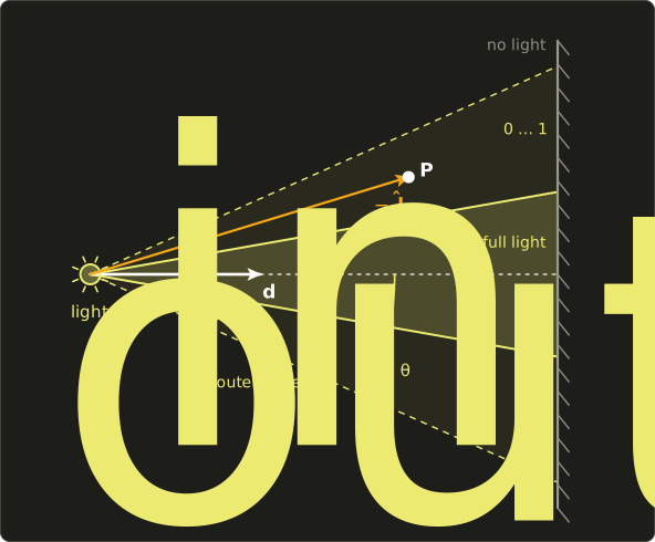
Notice the order of the edges.
Because the cosine of the bigger outer angle is the smaller number, is the first argument; smoothstep must have its first edge below the second (chapter 6 explained why reversing them is undefined).
Worked example with and :
10.2.3 In the shader
The spotlight reuses pointLight and multiplies the result by the cone factor:
// spotlight
const vec3 SPOT_POS = vec3(-0.8, 0.8, 1.6);           // position (top left, in front)
const vec3 SPOT_COLOR = vec3(1.0, 0.95, 0.8) * 1.5;   // color and brightness
const float COS_INNER = cos(radians(8.0));           // inner cone (full light up to here)
const float COS_OUTER = cos(radians(12.0));          // outer cone (no light beyond this)
// spotlight: a point light limited to a cone
//   dir: direction of the light axis (unit vector)
vec3 spotLight(vec3 pos, vec3 n, vec3 v, Material m, Light light, vec3 dir) {
  vec3 l = normalize(light.position - pos);
  float cosAngle = dot(-l, dir); // cosine of the angle between the axis and "light to surface"
  float cone = smoothstep(COS_OUTER, COS_INNER, cosAngle);
  return pointLight(pos, n, v, m, light) * cone;
}
const float COS_INNER = cos(radians(8.0)); is allowed: a built-in function called with constant arguments is a constant expression, and the compiler computes it once.
This works in every GLSL version we use, including macOS's 4.1.
Where should it point?
Let's aim it at a point on the wall that wanders around over time, or that follows the mouse.
The direction is "target minus position", normalized:
// 1: the spotlight follows the mouse, 0: it moves over time
#define FOLLOW_MOUSE 0
// mouse position in the same coordinates as p
vec2 mousePos() {
  return (2.0 * uMouse - uResolution) / uResolution.y;
}

// the point on the wall the spotlight aims at
vec3 spotTarget() {
#if FOLLOW_MOUSE
  return vec3(mousePos(), WALL_Z);
#else
  return vec3(0.8 * sin(uTime * 0.7), 0.4 * sin(uTime * 1.1), WALL_Z);
#endif
}
Two sine waves with different speeds (0.7 and 1.1) make a figure that doesn't repeat for a long time, so the spot seems to search the wall like a guard's flashlight.
In shade we add the spotlight after the point light:
vec3 shade(vec3 pos, vec3 n, Material m) {
  vec3 v = vec3(0.0, 0.0, 1.0); // towards the eye
  vec3 color = m.albedo * AMBIENT;
  // color += pointLight(pos, n, v, m, Light(orbit(0), LIGHT_COLOR, SHORT_RANGE));

  Light spot = Light(SPOT_POS, SPOT_COLOR, LONG_RANGE);
  vec3 spotDir = normalize(spotTarget() - SPOT_POS);
  color += spotLight(pos, n, v, m, spot, spotDir);
  return color;
}
I commented out the point light for the moment, so we can see the spotlight alone.
The spotlight is further away than the point light (about 2.5 units from the wall), so it gets the long-range attenuation.
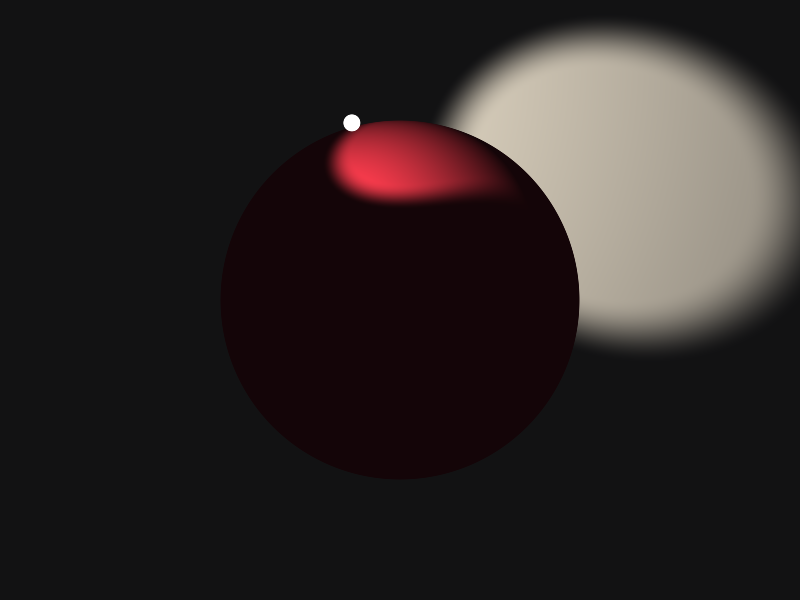
The spot on the wall is an oval, not a circle, because the light hits the wall at an angle.
And the sphere doesn't block any light: when the cone passes behind it, the wall there is still lit.
We have no shadows; a light reaches every point that faces it.
Shadows need to know what lies between the light and the surface, which comes with raymarching in chapter 14 and with shadow maps in the OpenGL series.
Uncomment the point light again and both lights add up.
10.3 Hemisphere lights
10.3.1 Ambient light with a direction
Our ambient term is still m.albedo * AMBIENT: the same amount of light from everywhere.
Outdoors that is clearly wrong.
The sky above is bright and bluish, the ground below is darker and has the colour of grass, sand or stone.
A surface facing up sees mostly sky, a surface facing down sees mostly ground, and a vertical wall sees half of each.
The hemisphere light models exactly this, with two colours and one direction, "up":
goes from −1 (facing straight down) to 1 (facing straight up), and maps that to 0 to 1.
This is not just a cheap trick: if the whole upper half of the world has one brightness and the lower half another, the light a matte surface receives from them is exactly of the sky plus of the ground, where is the angle between the normal and up.
That is our formula.
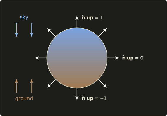
Worked example with and :
- Facing up, : , ambient = sky = .
- Facing sideways, : , ambient = , half of each.
- Facing mostly down, : , ambient = .
10.3.2 In the shader
// hemisphere light
const vec3 SKY = vec3(0.15, 0.2, 0.3);       // light from above (sky)
const vec3 GROUND = vec3(0.1, 0.07, 0.05);   // light from below (ground)
const vec3 UP = vec3(0.0, 1.0, 0.0);
// hemisphere light: sky color facing up, ground color facing down
vec3 hemisphere(vec3 n) {
  float t = 0.5 + 0.5 * dot(n, UP);
  return mix(GROUND, SKY, t);
}
And in shade the first line becomes:
vec3 color = m.albedo * hemisphere(n);
mix(a, b, t) is the linear interpolation from chapter 3, here between two colours.
The AMBIENT constant is no longer needed.
To see what changed, here is the ambient part alone, flat on the left and hemisphere on the right (both four times brighter than in the scene, so you can see them):
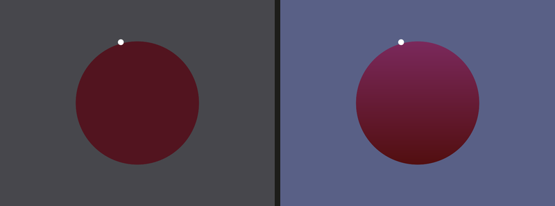
The flat ambient light makes the sphere a flat disc where no light shines.
The hemisphere light keeps it round even in the shadow: the top is lit by the bluish sky, the bottom by the brownish ground.
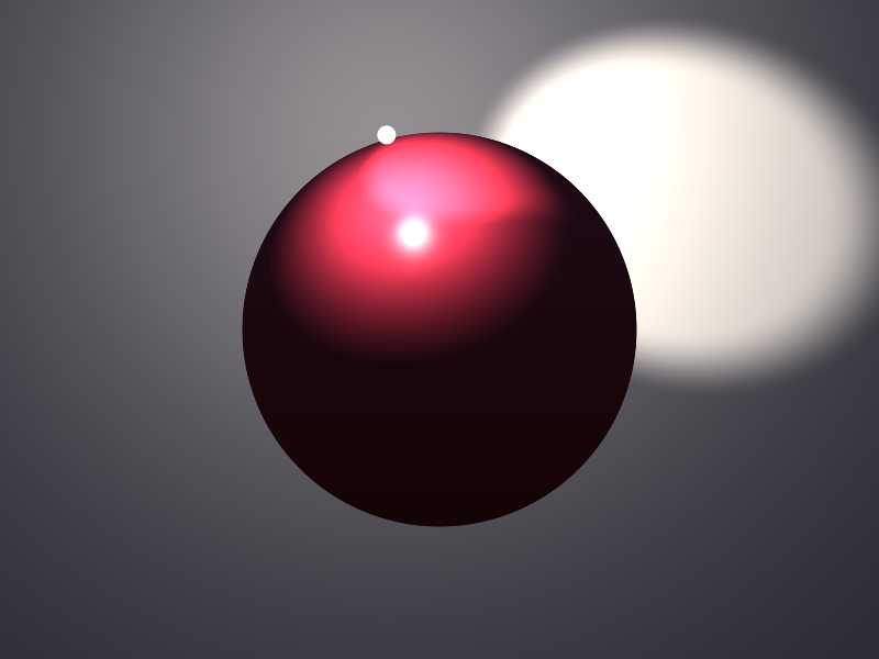
Here is the whole scene with the point light, the spotlight and the hemisphere light:
10.4 Many lights
10.4.1 A constant array and a loop
Now three coloured point lights, red, green and blue, circling the sphere 120° apart.
We could write three pointLight calls, but with an array and a loop the number of lights is one constant:
// circling point lights (red, green, blue)
const int NUM_LIGHTS = 3;
const vec3 LIGHT_COLORS[NUM_LIGHTS] = vec3[NUM_LIGHTS](
  vec3(1.0, 0.15, 0.1) * 3.0,
  vec3(0.1, 1.0, 0.15) * 3.0,
  vec3(0.15, 0.3, 1.0) * 3.0
);
  vec3 color = m.albedo * hemisphere(n);

  for (int i = 0; i < NUM_LIGHTS; ++i) {
    Light light = Light(orbit(i), LIGHT_COLORS[i], SHORT_RANGE);
    color += pointLight(pos, n, v, m, light);
  }
(The single LIGHT_COLOR constant is no longer needed.)
vec3[NUM_LIGHTS](...) is an array constructor: the type, the size in brackets, and then the elements.
The size of an array must be a constant expression, so NUM_LIGHTS has to be a const int.
The marker loop in main draws a dot for every light:
  // light markers (a dot for each point light)
  float marker = 0.0;
  for (int i = 0; i < NUM_LIGHTS; ++i) {
    marker = max(marker, 1.0 - smoothstep(0.03 - px, 0.03, length(p - orbit(i).xy)));
  }
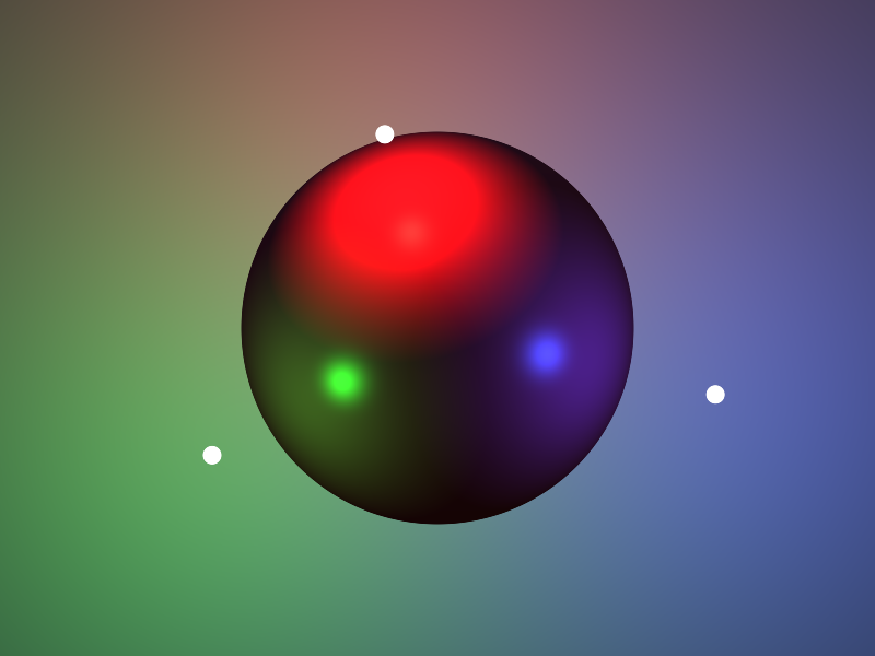
Where the red and green light overlap on the wall, the wall turns yellowish: light simply adds up.
That is what makes lighting with several lights so easy, and it is also the reason for the problems in 10.6 and 10.7.
10.4.2 Light data from C: uniform arrays
In a game the lights come from the level, so their data has to come from the CPU.
A uniform can be an array too.
Here is how the colours would come from C instead (this is only an example, it is not part of the chapter's diff).
In the shader, the constant array becomes:
const int NUM_LIGHTS = 3;
uniform vec3 uLightColors[NUM_LIGHTS]; // set from C
and the loop uses uLightColors[i].
In main.c, next to the other uniforms:
    // pass the light colours as an array (3 vec3 = 9 floats)
    float lightColors[] = {
      3.0f, 0.45f, 0.3f,
      0.3f, 3.0f, 0.45f,
      0.45f, 0.9f, 3.0f
    };
    glUniform3fv(glGetUniformLocation(shaderProgram, "uLightColors"), 3, lightColors);
glUniform3fv(location, count, pointer) uploads count vec3 values, three floats each, starting at the array's first element.
I tested this: the picture is the same as with the constant array.
If you reload a shader that doesn't use uLightColors, glGetUniformLocation returns −1, and OpenGL silently ignores uniform calls with location −1, so the tester keeps working.
The number of uniforms is limited (GL_MAX_FRAGMENT_UNIFORM_COMPONENTS, at least 1024 floats in OpenGL 4.x), and every light costs work in every pixel.
Real engines therefore put light data into uniform buffer objects or shader storage buffers, and only process the lights that can reach a pixel.
The OpenGL series shows how.
10.5 Area lights
10.5.1 Why points are not enough
Real lights are not points.
A window, a fluorescent tube, a TV screen or the softbox in a photo studio has a size, and you can see it in two ways:
- Soft shadows and soft light: a point near a big light is lit from many directions at once.
- Highlights with the shape of the light: a shiny ball under a tube light shows a long streak, not a dot. Look at a car in a street at night.
The exact answer for an area light is an integral: add up the light from every point of the surface of the light.
GPUs can't do integrals, so real-time renderers approximate.
We will light the scene with a tube light, a glowing line segment from to , and try the two classic approximations.
10.5.2 Many point lights
The obvious approach: put point lights along the segment and give each one of the light.
Sample (from 0 to ) sits at
The puts each sample in the middle of its piece of the segment instead of at its start.
This works well for the diffuse light, which changes slowly over the surface.
For specular light it works badly: each sample makes its own little highlight, and unless is very large you see a row of dots instead of a line.
Here is the highlight of the tube light on a very shiny sphere (shininess 256): 4 samples, 64 samples, and the method from the next section:

64 samples give the correct shape but cost 64 lights per pixel.
10.5.3 The representative point
Brian Karis described a much cheaper trick for specular light in "Real Shading in Unreal Engine 4" (2013).
A highlight is the reflection of the light.
So find the reflection ray, , the direction in which the surface mirrors the eye, and take the point on the light that is closest to that ray.
Then use that one point as an ordinary point light for the specular term.
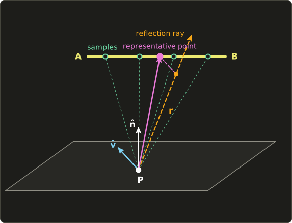
To find the closest point, work relative to the surface point : let and , so the points of the tube are for .
The squared distance of from the ray through with unit direction is "length squared minus the part along the ray squared" (projection, linear algebra chapter 4):
At the minimum the derivative is zero.
Since :
Then we clamp to so the point stays on the tube.
The denominator is zero only when the ray is parallel to the tube; a max(..., 1e-6) protects us from dividing by zero there.
10.5.4 In the shader
Diffuse with samples, specular with the representative point:
// tube light (a line segment from A to B)
const vec3 TUBE_A = vec3(-0.5, 0.4, 0.9);
const vec3 TUBE_B = vec3(0.5, 0.4, 0.9);
const vec3 TUBE_COLOR = vec3(1.0, 0.9, 0.7) * 1.0;
const int TUBE_SAMPLES = 16;
// tube light (line segment from A to B)
vec3 tubeLight(vec3 pos, vec3 n, vec3 v, Material m, vec3 a, vec3 b, vec3 lightColor) {
  // diffuse: average of TUBE_SAMPLES point lights along the segment
  float diffuse = 0.0;
  for (int i = 0; i < TUBE_SAMPLES; ++i) {
    float t = (float(i) + 0.5) / float(TUBE_SAMPLES);
    vec3 toLight = mix(a, b, t) - pos;
    float d = length(toLight);
    diffuse += max(dot(n, toLight / d), 0.0) * attenuate(d, MEDIUM_RANGE);
  }
  diffuse /= float(TUBE_SAMPLES);

  // specular: only the point on the segment closest to the reflection ray
  vec3 r = reflect(-v, n);
  vec3 l0 = a - pos;
  vec3 ld = b - a;
  float rd = dot(r, ld);
  float t = (dot(r, l0) * rd - dot(l0, ld)) / max(dot(ld, ld) - rd * rd, 1e-6);
  vec3 toLight = l0 + clamp(t, 0.0, 1.0) * ld;
  float d = length(toLight);
  vec3 l = toLight / d;
  float specular = 0.0;
  if (dot(n, l) > 0.0) specular = pow(max(dot(n, normalize(l + v)), 0.0), m.shininess);
  specular *= attenuate(d, MEDIUM_RANGE);

  return (m.albedo * diffuse + m.specular * specular) * lightColor;
}
In GLSL, float(i) converts the loop counter to a float; there is no automatic conversion from int to float in a division like i / TUBE_SAMPLES (that would be an integer division, chapter 2).
mix works on vectors too: mix(a, b, t) is the point at fraction between A and B.
Notice that the reflection uses reflect(-v, n): this time we mirror the eye direction, because we are asking "what does the surface show in its mirror?"
In shade, comment out the point lights and the spotlight and add the tube:
color += tubeLight(pos, n, v, m, TUBE_A, TUBE_B, TUBE_COLOR);
and draw the tube as a line with sdSegment from chapter 6, after the point markers in main:
// distance to the segment ab (chapter 6)
float sdSegment(vec2 p, vec2 a, vec2 b) {
  vec2 pa = p - a;
  vec2 ba = b - a;
  float h = clamp(dot(pa, ba) / dot(ba, ba), 0.0, 1.0);
  return length(pa - ba * h);
}
  // a line for the tube light
  float tube = sdSegment(p, TUBE_A.xy, TUBE_B.xy);
  marker = max(marker, 1.0 - smoothstep(0.015 - px, 0.015, tube));
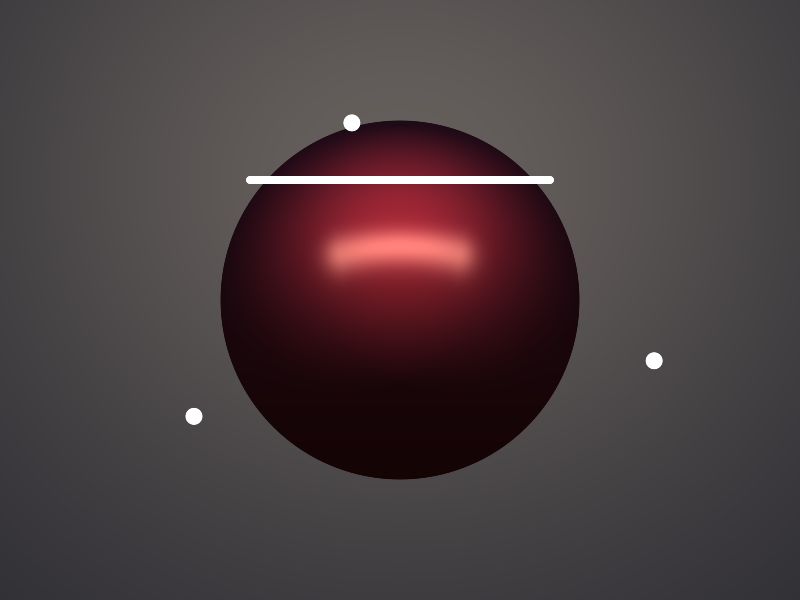
The highlight is a curved streak: a straight tube mirrored in a sphere, like a neon sign in a Christmas ball.
The light on the wall is broad and soft, without the bright centre of a point light.
The representative point is a cheat, and it has a price.
It takes the light of the whole tube from the brightest point, so a long tube gives a highlight that is too bright compared to the sampled one; Karis adds a normalization factor for that, which we skip here.
For rectangular lights (windows, screens), modern engines use a more accurate method called linearly transformed cosines (Heitz and others, 2016), which is beyond this series.
10.6 Energy and over-exposure
10.6.1 Everything together
Now switch everything on in shade: hemisphere, three point lights, the spotlight and the tube.
  vec3 color = m.albedo * hemisphere(n);

  for (int i = 0; i < NUM_LIGHTS; ++i) {
    Light light = Light(orbit(i), LIGHT_COLORS[i], SHORT_RANGE);
    color += pointLight(pos, n, v, m, light);
  }

  Light spot = Light(SPOT_POS, SPOT_COLOR, LONG_RANGE);
  vec3 spotDir = normalize(spotTarget() - SPOT_POS);
  color += spotLight(pos, n, v, m, spot, spotDir);

  color += tubeLight(pos, n, v, m, TUBE_A, TUBE_B, TUBE_COLOR);
  return color;
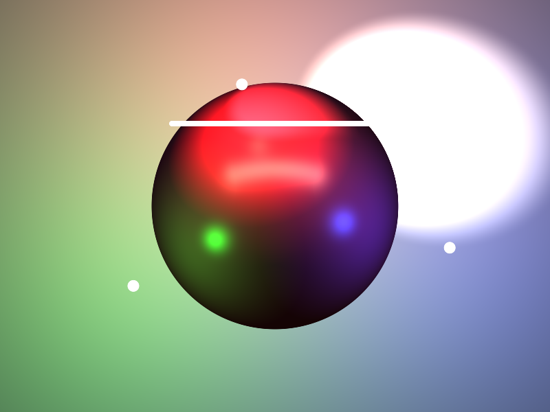
It looks wrong, and it is wrong in an instructive way.
Each light alone was fine, but light adds up, and the sum is often far above 1.0.
The framebuffer stores 0 to 1 per channel, so everything above 1 is simply cut off (clamped).
That has two bad effects:
- Detail disappears. 1.5 and 5.0 both become 1.0, so the spot is a flat white blob without the soft edge we built.
- Colours change. A light red of is clamped to : the ratio between the channels was 10 to 1.5 to 1, now it is 2.5 to 1.5 to 1. Bright colours become pale and wrong, and very bright ones turn white.
Turning all lights down would fix the bright parts and make the rest too dark.
Photographers know this problem as dynamic range: the real world has a far larger range of brightness than paper or a screen.
10.6.2 Tone mapping
The solution is to treat the computed colour as a physical amount of light, from 0 to as much as you like, and only at the very end squeeze it into 0 to 1 with a curve.
That curve is called a tone mapping operator.
The simplest good one is Reinhard's (2002):
For small values it does almost nothing (), 1 becomes 0.5, 3 becomes 0.75, 9 becomes 0.9, and nothing ever reaches 1.
Bright things are compressed, but stay brighter than less bright things: the detail survives.
Our light red becomes : still clearly red.
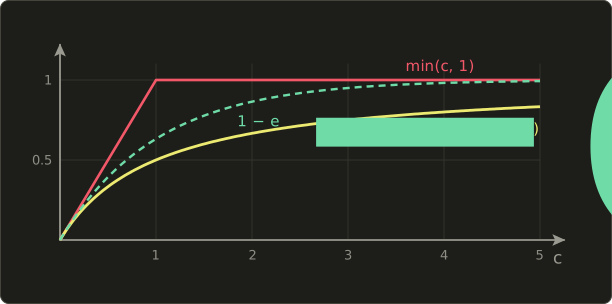
It is one line, at the end of main after mixing wall and sphere:
  // tone mapping (Reinhard): squeeze 0..infinity into 0..1
  color = color / (1.0 + color);
Dividing two vec3 divides each component, so this is Reinhard per channel.
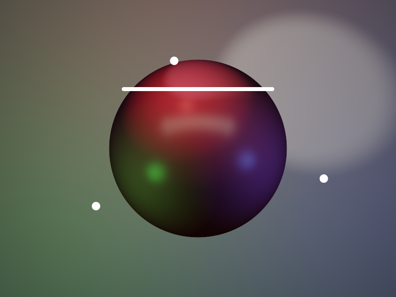
The picture is a bit greyer overall, because Reinhard also darkens the mid tones (1.0 becomes 0.5).
Real engines use curves shaped like the response of photographic film ("filmic" curves; ACES, from the film industry, is a common one) together with an exposure factor, which multiplies the colour before the curve, like a camera's exposure setting.
Strictly speaking, Blinn-Phong also does not conserve energy: a sharper highlight (higher shininess) should be brighter, because the same reflected light is concentrated in a smaller spot.
Physically based versions multiply the specular term by for that reason.
We keep the simple version, but this is one of the reasons the industry moved to physically based models.
10.7 Gamma correction
10.7.1 What the numbers in a framebuffer mean
Here is the last and sneakiest problem.
We have treated a colour value of 0.5 as "half as much light as 1.0".
But when the framebuffer contains 0.5 (128 out of 255), the monitor does not send out half the light of white.
It sends out about 22%.
The reason is history and our eyes.
Our eyes are much more sensitive to differences between dark tones than between bright ones.
If 8 bits were spread evenly over the amount of light, most of the 256 steps would be spent on bright tones we can hardly tell apart, and the dark tones would show visible bands.
So images are stored in a non-linear encoding, the sRGB standard, that spends more of the steps on dark tones.
Old CRT monitors happened to have almost exactly the inverse response, so the value went straight to the screen; today's monitors imitate that on purpose.
As a good approximation, the monitor shows the amount of light for a stored value as
and to show the amount of light correctly we have to store
Numbers: , so the value 0.5 shows about 22% of white.
The other way round, to show 50% of the light we need , which is 186 out of 255.
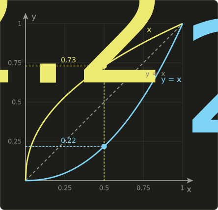
The exact sRGB curve is a little different from the pure power 2.2, with a short straight piece near black:
In GLSL:
// linear to sRGB (exact formula)
vec3 linearToSrgb(vec3 c) {
  vec3 lo = c * 12.92;
  vec3 hi = 1.055 * pow(c, vec3(1.0 / 2.4)) - 0.055;
  return mix(lo, hi, step(0.0031308, c));
}

// sRGB to linear (exact formula)
vec3 srgbToLinear(vec3 c) {
  vec3 lo = c / 12.92;
  vec3 hi = pow((c + 0.055) / 1.055, vec3(2.4));
  return mix(lo, hi, step(0.04045, c));
}
step(edge, x) (chapter 6) is 0 below the edge and 1 above it, per component, so mix(lo, hi, step(...)) picks one of the two formulas for each channel without an if.
I tried both versions in our scene: the largest difference to the simple pow(c, vec3(1.0 / 2.2)) was 9 out of 255 in a few dark pixels.
So the playground uses the simple power; use the exact functions when colours must match other software precisely.
10.7.2 Why lighting must happen in linear space
All our lighting math assumes that numbers are amounts of light: two lights add, half the cosine means half the light.
That is only true for linear values.
If we compute in linear values and send them to the monitor as they are, every result is shown darker than it should be, and wrongly so: a diffuse value of 0.2 should look like 20% of the light, but shows as .
That's why the dark side of our spheres fell off into black so quickly, and why we needed a lot of ambient light to make it look reasonable.
The rule of every modern renderer:
- Decode colours that were picked by eye or stored in images (sRGB) into linear values: .
- Do all lighting in linear values.
- Tone map.
- Encode the result for the monitor: .
Our albedo vec3(0.8, 0.2, 0.3) was picked by looking at it on a screen, so it is an sRGB colour: in linear values it is about .
Light colours and intensities like * 3.0 are physical amounts, so they are already linear and stay as they are.
10.7.3 Switching it on and off
To compare, we let the G key switch gamma correction on and off.
In main.c, next to reloadWasDown:
  int reloadWasDown = 0;
  int gammaOn = 1;       // gamma correction (toggle with G)
  int gammaWasDown = 0;
in the loop, after the R key:
    // G toggles gamma correction (for comparing)
    int gammaDown = glfwGetKey(window, GLFW_KEY_G) == GLFW_PRESS;
    if (gammaDown && !gammaWasDown) {
      gammaOn = !gammaOn;
      printf("Gamma correction: %s\n", gammaOn ? "on" : "off");
    }
    gammaWasDown = gammaDown;
and with the other uniforms:
glUniform1i(glGetUniformLocation(shaderProgram, "uGamma"), gammaOn);
It works exactly like the R key from chapter 5: we only react when the key goes from "up" to "down", otherwise holding G for a moment would toggle it on every frame.
A bool uniform is set with glUniform1i: 0 is false, anything else true.
(The project's main.c prints the message in Japanese, like all its other messages.)
In the shader:
uniform bool uGamma; // true: gamma correction on (toggle with G)
at the start of shade:
  vec3 v = vec3(0.0, 0.0, 1.0); // towards the eye
  if (uGamma) m.albedo = pow(m.albedo, vec3(2.2)); // sRGB color to linear
and at the end of main, after tone mapping and before drawing the markers:
  // gamma correction: linear values to sRGB for the monitor
  if (uGamma) color = pow(color, vec3(1.0 / 2.2));
m is a copy (an in parameter), so changing m.albedo in shade doesn't change the constant SPHERE.
pow works per component on vectors; the exponent must then be a vector too, vec3(2.2).
Gamma correction makes dark values much brighter (0.2 becomes 0.48), so with the same lights the scene would now look washed out.
I tuned the light values once more for the linear pipeline: point lights * 2.0 instead of 3.0, the spotlight * 1.0, the tube * 0.6, and a much darker sky and ground:
const vec3 SKY = vec3(0.04, 0.05, 0.08);      // light from above (sky)
const vec3 GROUND = vec3(0.02, 0.015, 0.01);  // light from below (ground)
This retuning is normal: values tuned without gamma correction are tuned for the wrong curve.
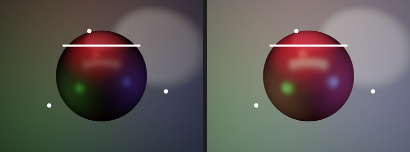
Press G a few times and watch the dark side of the sphere.
Without correction the light falls off a cliff into black; with correction it rolls off gently, like light on a real ball.
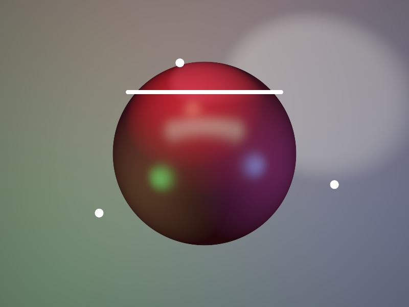
Here is the final scene:
10.7.4 Letting the hardware do it
Doing the conversion in the shader is clear for learning, but GPUs can do both directions for free:
- sRGB textures (
GL_SRGB8_ALPHA8, chapter 11): the GPU decodes to linear when the shader samples them, before filtering, which is also more correct. - sRGB framebuffers: with
glEnable(GL_FRAMEBUFFER_SRGB)and a framebuffer that is sRGB-capable, OpenGL encodes the shader's linear output when it writes it. In Vulkan you pick a swapchain format likeVK_FORMAT_B8G8R8A8_SRGB.
The one mistake to avoid is doing it twice.
If the framebuffer already encodes and your shader also applies pow(c, 1.0 / 2.2), the image looks washed out and grey; if nobody encodes, it looks too dark and contrasty.
When an image looks "off" in one of those two ways, check the gamma chain first.
10.8 New GLSL features in this chapter
| Feature | What it does |
|---|---|
radians(x), degrees(x) |
degrees to radians, , and back |
T name[N] |
an array of N elements; N must be a constant expression |
vec3[N](a, b, c) |
array constructor: the elements in order |
name.length() |
the number of elements of an array |
uniform vec3 u[N] |
a uniform array, set from C with glUniform3fv(loc, N, data) |
uniform bool u |
a boolean uniform, set with glUniform1i (0 = false) |
float(i) |
converts an int to a float (no automatic conversion in GLSL) |
step(e, x) on vectors |
per component, 0 below e, 1 from e on |
pow(v, vec3(e)) |
per component power on a vector |
- Constant expressions may call built-in functions with constant arguments, like
cos(radians(8.0)). Texture functions are the exception. - Loops with a variable number of iterations are allowed in desktop GLSL. Loops with a constant count, like ours, are often unrolled completely by the compiler.
- GLSL ES 1.00 (WebGL 1) only allows array indexing with constants or loop counters in fragment shaders; desktop GLSL and GLSL ES 3.00 are more relaxed.
- Everything in this chapter works on macOS's OpenGL 4.1.
10.9 How this is used in real games and engines
- Spotlights are everywhere: car headlights, street lamps, stage lights and above all the flashlight of horror and stealth games. Engines add a cookie (a texture projected through the cone, chapter 11) for patterned light, and shadow maps (OpenGL series) so the light is blocked by objects. Unity and Unreal both expose inner and outer cone angles exactly like ours.
- Hemisphere and sky ambient. Unity's "Gradient" ambient mode uses a sky, an equator and a ground colour, a three-colour version of our hemisphere light. Many engines go further and store the ambient light of a whole environment as spherical harmonics, a handful of numbers per probe that can represent any smooth distribution of light around a point; the hemisphere light is the simplest case of that idea.
- Area lights. Unreal Engine uses the representative point method from Karis's paper for spherical and tube lights. Rectangular area lights in Unity's HDRP and other modern renderers use linearly transformed cosines. Studio-style lighting in product configurators and car games relies heavily on area lights for their soft, shaped reflections.
- Many lights. Deferred and clustered (Forward+) renderers make hundreds or thousands of lights affordable by only evaluating the lights that can reach each pixel or each cell of the screen.
- HDR and gamma. Every modern game renders in linear HDR (16-bit float framebuffers) and tone maps at the end, often with an adjustable exposure ("eye adaptation") and a filmic curve. And every texture with colours is marked as sRGB so the GPU decodes it.
10.10 Summary
- Spotlight: , and for a soft edge. Compare cosines; never call
acosper pixel. - Hemisphere light: ; exact for the diffuse light from a two-coloured sky.
- Area lights: average several point samples for diffuse light; for specular light, use the point on the light closest to the reflection ray (representative point).
- Lights add up. Use structs, constant arrays (
vec3[N](...)) or uniform arrays (glUniform3fv) and loops. - Values above 1 get clipped. Tone map at the end, for example with Reinhard .
- Monitors show . Decode sRGB colours to linear, light in linear, tone map, then encode with , exactly once.
10.11 Challenges
- ★ A spotlight has and . Compute the cone factor for , and by hand (use , , ). You should get 1, about 0.57 and 0.
- ★ With gamma 2.2: which stored value shows 25% of white's light, and how much light does the stored value 0.25 show? Then apply Reinhard to , and and encode each result with . (The first two answers are about 0.533 and 0.047.)
- ★★ Make the spotlight a flashlight held by the viewer: put it at
vec3(mousePos(), 2.0)and point it straight into the scene,vec3(0.0, 0.0, -1.0). Use cones of 10° and 14°. Moving the mouse should move a round spot over sphere and wall; on the sphere the spot is distorted by the curvature. - ★★ Give the hemisphere light a third colour for the horizon, like Unity's gradient mode: mix from ground to horizon for from −1 to 0 and from horizon to sky from 0 to 1. With a bright orange horizon, the left and right edges of the sphere should glow like a sunset.
- ★★ Put the three point light colours into a uniform array as shown in 10.4.2 and make the C code change them over time, for example by rotating the hues with
sinas in chapter 3. The lights should slowly change colour while they circle. - ★★ Replace Reinhard with the exponential curve (
1.0 - exp(-exposure * color)) and add an exposure that changes with the mouse x position from 0.25 to 4. Find the exposure where the image looks most like the Reinhard version. - ★★★ Turn the tube light into a rectangular light (a window): sample its diffuse light on a 4 × 4 grid, and for the specular light find the representative point by intersecting the reflection ray with the rectangle's plane and clamping the hit point to the rectangle. The sphere should show a rectangular highlight, like a window reflected in a Christmas ball. Why is clamping the hit point a worse approximation when the ray misses the rectangle by a lot?
ファイル: a/main.c | b/main.c
| 前 | 新 | ||
|---|---|---|---|
| @@ -262,6 +262,8 @@ int main(int argc, char **argv) { | |||
| 262 | glEnableVertexAttribArray(1); | 262 | glEnableVertexAttribArray(1); |
| 263 | 263 | ||
| 264 | int reloadWasDown = 0; | 264 | int reloadWasDown = 0; |
| 265 | int gammaOn = 1; // ガンマ補正(Gキーで切り替え) | ||
| 266 | int gammaWasDown = 0; | ||
| 265 | 267 | ||
| 266 | // メインレンダリングループ | 268 | // メインレンダリングループ |
| 267 | while (!glfwWindowShouldClose(window)) { | 269 | while (!glfwWindowShouldClose(window)) { |
| @@ -282,6 +284,14 @@ int main(int argc, char **argv) { | |||
| 282 | } | 284 | } |
| 283 | reloadWasDown = reloadDown; | 285 | reloadWasDown = reloadDown; |
| 284 | 286 | ||
| 287 | // Gキーでガンマ補正を切り替える(比較用) | ||
| 288 | int gammaDown = glfwGetKey(window, GLFW_KEY_G) == GLFW_PRESS; | ||
| 289 | if (gammaDown && !gammaWasDown) { | ||
| 290 | gammaOn = !gammaOn; | ||
| 291 | printf("ガンマ補正: %s\n", gammaOn ? "オン" : "オフ"); | ||
| 292 | } | ||
| 293 | gammaWasDown = gammaDown; | ||
| 294 | |||
| 285 | // 画面をクリア | 295 | // 画面をクリア |
| 286 | glClearColor(0.0f, 0.0f, 0.0f, 1.0f); | 296 | glClearColor(0.0f, 0.0f, 0.0f, 1.0f); |
| 287 | glClear(GL_COLOR_BUFFER_BIT); | 297 | glClear(GL_COLOR_BUFFER_BIT); |
| @@ -301,6 +311,7 @@ int main(int argc, char **argv) { | |||
| 301 | glUniform2f(glGetUniformLocation(shaderProgram, "uResolution"), (float)gWidth, (float)gHeight); | 311 | glUniform2f(glGetUniformLocation(shaderProgram, "uResolution"), (float)gWidth, (float)gHeight); |
| 302 | glUniform2f(glGetUniformLocation(shaderProgram, "uMouse"), | 312 | glUniform2f(glGetUniformLocation(shaderProgram, "uMouse"), |
| 303 | (float)mouseX * scale, (float)(windowH - mouseY) * scale); | 313 | (float)mouseX * scale, (float)(windowH - mouseY) * scale); |
| 314 | glUniform1i(glGetUniformLocation(shaderProgram, "uGamma"), gammaOn); | ||
| 304 | 315 | ||
| 305 | // クアッドを描画 | 316 | // クアッドを描画 |
| 306 | glBindVertexArray(VAO); | 317 | glBindVertexArray(VAO); |
ファイル: a/shader/playground.glsl | b/shader/playground.glsl
| 前 | 新 | ||
|---|---|---|---|
| @@ -6,8 +6,9 @@ out vec4 out_color; | |||
| 6 | uniform float uTime; // 起動してからの秒数 | 6 | uniform float uTime; // 起動してからの秒数 |
| 7 | uniform vec2 uResolution; // 画面の大きさ(ピクセル) | 7 | uniform vec2 uResolution; // 画面の大きさ(ピクセル) |
| 8 | uniform vec2 uMouse; // マウスの位置(ピクセル、左下が原点) | 8 | uniform vec2 uMouse; // マウスの位置(ピクセル、左下が原点) |
| 9 | uniform bool uGamma; // trueならガンマ補正する(Gキーで切り替え) | ||
| 9 | 10 | ||
| 10 | // 1にするとマウスで光を動かす、0にすると時間で光が回る | 11 | // 1にするとスポットライトがマウスを追う、0にすると時間で動く |
| 11 | #define FOLLOW_MOUSE 0 | 12 | #define FOLLOW_MOUSE 0 |
| 12 | 13 | ||
| 13 | // 表面の材質 | 14 | // 表面の材質 |
| @@ -17,15 +18,54 @@ struct Material { | |||
| 17 | float shininess; // 光沢度(大きい程ハイライトが小さく鋭い) | 18 | float shininess; // 光沢度(大きい程ハイライトが小さく鋭い) |
| 18 | }; | 19 | }; |
| 19 | 20 | ||
| 21 | // 光源 | ||
| 22 | struct Light { | ||
| 23 | vec3 position; // 位置 | ||
| 24 | vec3 color; // 色と明るさ | ||
| 25 | vec3 attenuation; // 減衰の定数(定数項、1次、2次) | ||
| 26 | }; | ||
| 27 | |||
| 20 | const float RADIUS = 0.6; // 球の半径 | 28 | const float RADIUS = 0.6; // 球の半径 |
| 21 | const float WALL_Z = -RADIUS; // 壁の位置(球の真後ろ) | 29 | const float WALL_Z = -RADIUS; // 壁の位置(球の真後ろ) |
| 22 | const float AMBIENT = 0.1; // アンビエントの強さ | ||
| 23 | const vec3 LIGHT_COLOR = vec3(1.0, 0.95, 0.85) * 3.0; // 光の色と明るさ | ||
| 24 | const vec3 ATTENUATION = vec3(1.0, 0.7, 1.8); // 減衰の定数(定数項、1次、2次) | ||
| 25 | 30 | ||
| 26 | const Material SPHERE = Material(vec3(0.8, 0.2, 0.3), 0.5, 64.0); | 31 | const Material SPHERE = Material(vec3(0.8, 0.2, 0.3), 0.5, 64.0); |
| 27 | const Material WALL = Material(vec3(0.7, 0.7, 0.75), 0.1, 8.0); | 32 | const Material WALL = Material(vec3(0.7, 0.7, 0.75), 0.1, 8.0); |
| 28 | 33 | ||
| 34 | // 減衰の定数(第9章の表から) | ||
| 35 | const vec3 SHORT_RANGE = vec3(1.0, 0.7, 1.8); // 近くだけを照らす | ||
| 36 | const vec3 MEDIUM_RANGE = vec3(1.0, 0.35, 0.44); // 中くらい | ||
| 37 | const vec3 LONG_RANGE = vec3(1.0, 0.09, 0.032); // 遠くまで届く | ||
| 38 | |||
| 39 | // スポットライト | ||
| 40 | const vec3 SPOT_POS = vec3(-0.8, 0.8, 1.6); // 位置(左上手前) | ||
| 41 | const vec3 SPOT_COLOR = vec3(1.0, 0.95, 0.8) * 1.0; // 色と明るさ | ||
| 42 | const float COS_INNER = cos(radians(8.0)); // 内側の円錐(此処までは全力) | ||
| 43 | const float COS_OUTER = cos(radians(12.0)); // 外側の円錐(此処から外は真っ暗) | ||
| 44 | |||
| 45 | // ヘミスフィアライト | ||
| 46 | const vec3 SKY = vec3(0.04, 0.05, 0.08); // 上から来る光(空) | ||
| 47 | const vec3 GROUND = vec3(0.02, 0.015, 0.01); // 下から来る光(地面) | ||
| 48 | const vec3 UP = vec3(0.0, 1.0, 0.0); | ||
| 49 | |||
| 50 | // 回るポイントライト(赤、緑、青) | ||
| 51 | const int NUM_LIGHTS = 3; | ||
| 52 | const vec3 LIGHT_COLORS[NUM_LIGHTS] = vec3[NUM_LIGHTS]( | ||
| 53 | vec3(1.0, 0.15, 0.1) * 2.0, | ||
| 54 | vec3(0.1, 1.0, 0.15) * 2.0, | ||
| 55 | vec3(0.15, 0.3, 1.0) * 2.0 | ||
| 56 | ); | ||
| 57 | |||
| 58 | // チューブライト(AからBまでの線分の光源) | ||
| 59 | const vec3 TUBE_A = vec3(-0.5, 0.4, 0.9); | ||
| 60 | const vec3 TUBE_B = vec3(0.5, 0.4, 0.9); | ||
| 61 | const vec3 TUBE_COLOR = vec3(1.0, 0.9, 0.7) * 0.6; | ||
| 62 | const int TUBE_SAMPLES = 16; | ||
| 63 | |||
| 64 | // 距離dでの減衰(kは定数項、1次、2次) | ||
| 65 | float attenuate(float d, vec3 k) { | ||
| 66 | return 1.0 / (k.x + k.y * d + k.z * d * d); | ||
| 67 | } | ||
| 68 | |||
| 29 | // 1つの光からの拡散反射と鏡面反射(ブリン・フォン) | 69 | // 1つの光からの拡散反射と鏡面反射(ブリン・フォン) |
| 30 | // n:法線、v:目への向き、l:光への向き(全て単位ベクトル) | 70 | // n:法線、v:目への向き、l:光への向き(全て単位ベクトル) |
| 31 | vec3 blinnPhong(vec3 n, vec3 v, vec3 l, Material m, vec3 lightColor) { | 71 | vec3 blinnPhong(vec3 n, vec3 v, vec3 l, Material m, vec3 lightColor) { |
| @@ -38,20 +78,102 @@ vec3 blinnPhong(vec3 n, vec3 v, vec3 l, Material m, vec3 lightColor) { | |||
| 38 | return (m.albedo * diffuse + m.specular * specular) * lightColor; | 78 | return (m.albedo * diffuse + m.specular * specular) * lightColor; |
| 39 | } | 79 | } |
| 40 | 80 | ||
| 41 | // ポイントライト:光の位置から向きと減衰を求める | 81 | // ポイントライト |
| 42 | vec3 pointLight(vec3 pos, vec3 n, vec3 v, Material m, vec3 lightPos, vec3 lightColor) { | 82 | vec3 pointLight(vec3 pos, vec3 n, vec3 v, Material m, Light light) { |
| 43 | vec3 toLight = lightPos - pos; | 83 | vec3 toLight = light.position - pos; |
| 44 | float d = length(toLight); // 光までの距離 | 84 | float d = length(toLight); |
| 45 | vec3 l = toLight / d; // normalize(toLight)と同じ | 85 | vec3 l = toLight / d; |
| 46 | float attenuation = 1.0 / (ATTENUATION.x + ATTENUATION.y * d + ATTENUATION.z * d * d); | 86 | return blinnPhong(n, v, l, m, light.color) * attenuate(d, light.attenuation); |
| 47 | return blinnPhong(n, v, l, m, lightColor) * attenuation; | 87 | } |
| 88 | |||
| 89 | // スポットライト:ポイントライトを円錐の中だけにする | ||
| 90 | // dir:光軸の向き(単位ベクトル) | ||
| 91 | vec3 spotLight(vec3 pos, vec3 n, vec3 v, Material m, Light light, vec3 dir) { | ||
| 92 | vec3 l = normalize(light.position - pos); | ||
| 93 | float cosAngle = dot(-l, dir); // 光軸と「光から表面への向き」の間の角度のコサイン | ||
| 94 | float cone = smoothstep(COS_OUTER, COS_INNER, cosAngle); | ||
| 95 | return pointLight(pos, n, v, m, light) * cone; | ||
| 96 | } | ||
| 97 | |||
| 98 | // ヘミスフィアライト:法線が上を向く程空の色、下を向く程地面の色 | ||
| 99 | vec3 hemisphere(vec3 n) { | ||
| 100 | float t = 0.5 + 0.5 * dot(n, UP); | ||
| 101 | return mix(GROUND, SKY, t); | ||
| 102 | } | ||
| 103 | |||
| 104 | // チューブライト(AからBまでの線分) | ||
| 105 | vec3 tubeLight(vec3 pos, vec3 n, vec3 v, Material m, vec3 a, vec3 b, vec3 lightColor) { | ||
| 106 | // 拡散反射:線分上に並べたTUBE_SAMPLES個のポイントライトの平均 | ||
| 107 | float diffuse = 0.0; | ||
| 108 | for (int i = 0; i < TUBE_SAMPLES; ++i) { | ||
| 109 | float t = (float(i) + 0.5) / float(TUBE_SAMPLES); | ||
| 110 | vec3 toLight = mix(a, b, t) - pos; | ||
| 111 | float d = length(toLight); | ||
| 112 | diffuse += max(dot(n, toLight / d), 0.0) * attenuate(d, MEDIUM_RANGE); | ||
| 113 | } | ||
| 114 | diffuse /= float(TUBE_SAMPLES); | ||
| 115 | |||
| 116 | // 鏡面反射:反射ベクトルに一番近い線分上の点(代表点)だけを使う | ||
| 117 | vec3 r = reflect(-v, n); | ||
| 118 | vec3 l0 = a - pos; | ||
| 119 | vec3 ld = b - a; | ||
| 120 | float rd = dot(r, ld); | ||
| 121 | float t = (dot(r, l0) * rd - dot(l0, ld)) / max(dot(ld, ld) - rd * rd, 1e-6); | ||
| 122 | vec3 toLight = l0 + clamp(t, 0.0, 1.0) * ld; | ||
| 123 | float d = length(toLight); | ||
| 124 | vec3 l = toLight / d; | ||
| 125 | float specular = 0.0; | ||
| 126 | if (dot(n, l) > 0.0) specular = pow(max(dot(n, normalize(l + v)), 0.0), m.shininess); | ||
| 127 | specular *= attenuate(d, MEDIUM_RANGE); | ||
| 128 | |||
| 129 | return (m.albedo * diffuse + m.specular * specular) * lightColor; | ||
| 130 | } | ||
| 131 | |||
| 132 | // マウスの位置をpと同じ座標にする | ||
| 133 | vec2 mousePos() { | ||
| 134 | return (2.0 * uMouse - uResolution) / uResolution.y; | ||
| 135 | } | ||
| 136 | |||
| 137 | // i番目のポイントライトの位置(120°ずつずれて回る) | ||
| 138 | vec3 orbit(int i) { | ||
| 139 | float a = uTime * 1.25 + float(i) * radians(120.0); | ||
| 140 | return vec3(0.9 * cos(a), 0.6 * sin(a), 0.7); | ||
| 141 | } | ||
| 142 | |||
| 143 | // スポットライトが狙う壁の点 | ||
| 144 | vec3 spotTarget() { | ||
| 145 | #if FOLLOW_MOUSE | ||
| 146 | return vec3(mousePos(), WALL_Z); | ||
| 147 | #else | ||
| 148 | return vec3(0.8 * sin(uTime * 0.7), 0.4 * sin(uTime * 1.1), WALL_Z); | ||
| 149 | #endif | ||
| 150 | } | ||
| 151 | |||
| 152 | // 線分abまでの距離(第6章) | ||
| 153 | float sdSegment(vec2 p, vec2 a, vec2 b) { | ||
| 154 | vec2 pa = p - a; | ||
| 155 | vec2 ba = b - a; | ||
| 156 | float h = clamp(dot(pa, ba) / dot(ba, ba), 0.0, 1.0); | ||
| 157 | return length(pa - ba * h); | ||
| 48 | } | 158 | } |
| 49 | 159 | ||
| 50 | // 表面の1点の色 | 160 | // 表面の1点の色 |
| 51 | vec3 shade(vec3 pos, vec3 n, Material m, vec3 lightPos) { | 161 | vec3 shade(vec3 pos, vec3 n, Material m) { |
| 52 | vec3 v = vec3(0.0, 0.0, 1.0); // 目への向き | 162 | vec3 v = vec3(0.0, 0.0, 1.0); // 目への向き |
| 53 | vec3 color = m.albedo * AMBIENT; | 163 | if (uGamma) m.albedo = pow(m.albedo, vec3(2.2)); // sRGBの色を線型にする |
| 54 | color += pointLight(pos, n, v, m, lightPos, LIGHT_COLOR); | 164 | |
| 165 | vec3 color = m.albedo * hemisphere(n); | ||
| 166 | |||
| 167 | for (int i = 0; i < NUM_LIGHTS; ++i) { | ||
| 168 | Light light = Light(orbit(i), LIGHT_COLORS[i], SHORT_RANGE); | ||
| 169 | color += pointLight(pos, n, v, m, light); | ||
| 170 | } | ||
| 171 | |||
| 172 | Light spot = Light(SPOT_POS, SPOT_COLOR, LONG_RANGE); | ||
| 173 | vec3 spotDir = normalize(spotTarget() - SPOT_POS); | ||
| 174 | color += spotLight(pos, n, v, m, spot, spotDir); | ||
| 175 | |||
| 176 | color += tubeLight(pos, n, v, m, TUBE_A, TUBE_B, TUBE_COLOR); | ||
| 55 | return color; | 177 | return color; |
| 56 | } | 178 | } |
| 57 | 179 | ||
| @@ -59,27 +181,31 @@ void main() { | |||
| 59 | vec2 p = (2.0 * gl_FragCoord.xy - uResolution) / uResolution.y; | 181 | vec2 p = (2.0 * gl_FragCoord.xy - uResolution) / uResolution.y; |
| 60 | float px = 2.0 / uResolution.y; | 182 | float px = 2.0 / uResolution.y; |
| 61 | 183 | ||
| 62 | // 光の位置(zは球より手前) | ||
| 63 | #if FOLLOW_MOUSE | ||
| 64 | vec2 mouse = (2.0 * uMouse - uResolution) / uResolution.y; // pと同じ座標にする | ||
| 65 | vec3 lightPos = vec3(mouse, 0.7); | ||
| 66 | #else | ||
| 67 | vec3 lightPos = vec3(0.9 * cos(uTime * 1.25), 0.6 * sin(uTime * 1.25), 0.7); | ||
| 68 | #endif | ||
| 69 | |||
| 70 | // 球 | 184 | // 球 |
| 71 | float z = sqrt(max(RADIUS * RADIUS - dot(p, p), 0.0)); | 185 | float z = sqrt(max(RADIUS * RADIUS - dot(p, p), 0.0)); |
| 72 | vec3 spherePos = vec3(p, z); | 186 | vec3 spherePos = vec3(p, z); |
| 73 | vec3 sphere = shade(spherePos, spherePos / RADIUS, SPHERE, lightPos); | 187 | vec3 sphere = shade(spherePos, spherePos / RADIUS, SPHERE); |
| 74 | 188 | ||
| 75 | // 壁(z = WALL_Zの平面、法線は手前を向く) | 189 | // 壁(z = WALL_Zの平面、法線は手前を向く) |
| 76 | vec3 wall = shade(vec3(p, WALL_Z), vec3(0.0, 0.0, 1.0), WALL, lightPos); | 190 | vec3 wall = shade(vec3(p, WALL_Z), vec3(0.0, 0.0, 1.0), WALL); |
| 77 | 191 | ||
| 78 | float mask = 1.0 - smoothstep(RADIUS - px, RADIUS, length(p)); | 192 | float mask = 1.0 - smoothstep(RADIUS - px, RADIUS, length(p)); |
| 79 | vec3 color = mix(wall, sphere, mask); | 193 | vec3 color = mix(wall, sphere, mask); |
| 80 | 194 | ||
| 81 | // 光の位置に小さな白い点を描く | 195 | // トーンマッピング(ラインハルト):0〜∞を0〜1に収める |
| 82 | float marker = 1.0 - smoothstep(0.03 - px, 0.03, length(p - lightPos.xy)); | 196 | color = color / (1.0 + color); |
| 197 | |||
| 198 | // ガンマ補正:線型の値をモニター用のsRGBにする | ||
| 199 | if (uGamma) color = pow(color, vec3(1.0 / 2.2)); | ||
| 200 | |||
| 201 | // 光源の印(ポイントライトは点) | ||
| 202 | float marker = 0.0; | ||
| 203 | for (int i = 0; i < NUM_LIGHTS; ++i) { | ||
| 204 | marker = max(marker, 1.0 - smoothstep(0.03 - px, 0.03, length(p - orbit(i).xy))); | ||
| 205 | } | ||
| 206 | // チューブライトは線 | ||
| 207 | float tube = sdSegment(p, TUBE_A.xy, TUBE_B.xy); | ||
| 208 | marker = max(marker, 1.0 - smoothstep(0.015 - px, 0.015, tube)); | ||
| 83 | color = mix(color, vec3(1.0), marker); | 209 | color = mix(color, vec3(1.0), marker); |
| 84 | 210 | ||
| 85 | out_color = vec4(color, 1.0); | 211 | out_color = vec4(color, 1.0); |
コメント(0)
まだコメントはありません。
ログインするとコメント出来ます。