7. Shape Models and Solid Representations
In chapters 4 to 6 we moved shapes around, projected them and turned them into pixels, but we never asked what a "shape" actually is inside the computer.
That's the topic of this chapter, the first of three on modeling (モデリング).
We'll see three levels of shape models, the classic ways to describe a solid object (set operations on primitives, the boundary, sweeps), the data structures that CAD programs use to walk around a boundary quickly, the counting rule that every valid solid obeys, and the local operations that chamfer and round its edges.
Why does this matter?
Every program that makes or uses 3D shapes has to store them somehow, and the choice decides which questions it can answer: a game only needs to draw the surface, but a CAD program has to know the volume of a part, whether two parts collide and how to round an edge without breaking the model.
For the exam, this chapter covers the first three items of syllabus area 3: shape models (形状モデル), solid representations (ソリッドモデルの形状表現) and boundary representation data structures and local deformation (境界表現のデータ構造と局所変形).
Curves and curved surfaces come in chapter 8, and polygon meshes, voxels and octrees in chapter 9; here they only appear where we need to point at them.
7.1 Three kinds of shape models
A shape model (形状モデル) is the description of an object's geometry that the computer stores.
Classic CAD distinguishes three levels, each one storing more than the one before:
- A wireframe model (ワイヤーフレームモデル) stores only vertices and the edges between them: a 3D line drawing.
- A surface model (サーフェスモデル) also stores the faces, so it knows where the surface of the object is, but not which side of that surface is "inside".
- A solid model (ソリッドモデル) knows the inside: for any point in space it can say whether the point is inside the object, outside, or on its surface.
The difference sounds small, but it decides what you can do.
Look at the twelve edges of a cube:
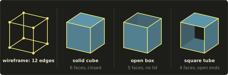
The solid cube, a box without a lid and a square tube open at both ends all have exactly the same twelve edges.
A wireframe model can't tell them apart, because the edges don't say which loops of edges are filled with a face.
On screen there's a second kind of ambiguity (曖昧さ): a wireframe drawing has no hidden lines, so you can't even tell which of the two squares is in front, and your eye flips between two readings while you look at it.
A surface model removes the first problem, because it stores the faces.
But it still doesn't say whether the open box is a thin sheet of cardboard or a heavy block with a cavity, because "inside" isn't part of it.
So the three models answer different questions:
| Question | Wireframe | Surface | Solid |
|---|---|---|---|
| Draw the edges quickly | yes | yes | yes |
| Draw shaded faces, remove hidden surfaces | no | yes | yes |
| Is this point inside the object? | no | no | yes |
| Volume, mass, center of gravity | no | no | yes |
| Do two parts collide (interference check, 干渉チェック)? | no | only where surfaces cross | yes |
| Generate cutting paths for a milling machine (CAM) | no | for the surface only | yes |
Where you meet them:
- Wireframes were the first 3D CAD displays (vector screens could only draw lines), and they are still the fast preview mode of every modeling program and the "show edges" overlay of a game engine.
- Surface models are what games and films draw: a triangle mesh only needs its surface to be shaded. Car bodies and other free-form shapes are also designed as surfaces (with the curved patches of chapter 8).
- Solid models are the base of mechanical CAD, CAM, 3D printing (a printer must know what to fill) and physical simulation.
In the rest of this chapter "solid" always means a solid model, and the question is how to store one.
7.2 Constructive solid geometry (CSG)
The first idea is to build complicated solids from simple ones, the way a machinist makes a part from a block of metal by adding and drilling.
Constructive solid geometry, CSG (CSG表現), describes a solid as simple primitives (プリミティブ: box, sphere, cylinder, cone, torus…, each with its size and placement) combined with the three set operations (集合演算):
- union (和) : everything in A or in B,
- difference (差) : everything in A but not in B,
- intersection (積) : everything in both.
The whole solid is stored as a CSG tree (CSG木): the leaves are primitives and every inner node is a set operation applied to its two children.
Here is a small bracket built from two boxes and a cylinder:
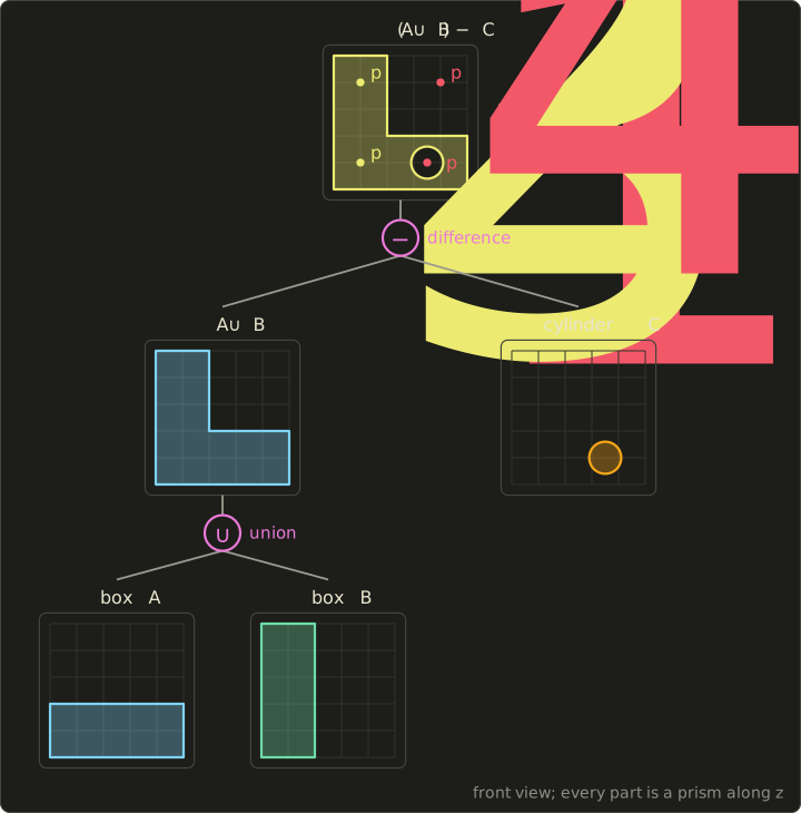
All three primitives are prisms along z, so the front view tells the whole story:
- box A: , , (the horizontal arm),
- box B: , , (the vertical arm),
- cylinder C: axis along z through , radius 0.6, from to .
The solid is .
Notice that the cylinder is longer than the plate is thick.
That's deliberate, and we'll see why in a moment.
Point membership classification: a worked example
The most basic question for a solid is "is this point inside?", and CSG answers it beautifully: ask the leaves, then combine the answers up the tree.
This is called point membership classification (点の内外判定).
Each primitive answers with one of three values, in (inside), on (on its surface) or out, and the operations combine them:
- union: in if either child says in; out if both say out,
- difference: in if the left child says in and the right child says out; out if the left says out or the right says in,
- intersection: in if both say in; out if either says out.
(When "on" is involved the answer is usually "on", with one subtle case we'll come back to.)
Let's classify four points, all at , the middle of the plate:
| Point | A | B | C | ||
|---|---|---|---|---|---|
| in | out | in | in | out | |
| out | in | in | out | in | |
| in | in | in | out | in | |
| out | out | out | out | out |
Take step by step.
Box A: , , , all strict, so in.
Box B: , so out.
Union: in.
Cylinder C: the squared distance from the axis is , and , so in.
Difference: the left child is in but the right child is also in, so out: is in the hole.
lies in the region where A and B overlap; the union simply says in, and the overlap is counted once, without any extra work.
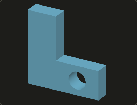
The same idea renders a CSG tree directly, without ever computing its boundary: shoot a ray through each pixel, find where it enters and leaves each primitive, and take the first point along the ray whose classification is "in" for the whole tree.
This picture of the bracket was made exactly like that (ray casting a CSG tree goes back to Roth's 1982 paper):
Regularized set operations
Ordinary set operations have a nasty side effect on solids.
Take two boxes that touch along a face, A from to and B from to .
Their ordinary intersection isn't empty: it's the shared face , a flat sheet with no volume.
In the cross-section below it's a line segment; in 3D it's a dangling face (宙に浮いた面): a face with solid on neither side.
No machinist would call that a part, and a B-rep built from it would be broken.
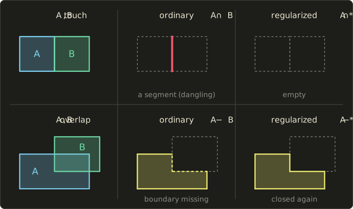
The fix is regularized set operations (正則化集合演算), written with a star:
and the same for and .
Here is the interior (内部: the set without its boundary) and the bar is the closure (閉包: the set plus its boundary).
Taking the interior throws away everything that has no thickness (the shared face has no interior points), and taking the closure puts the boundary back on what's left.
For the touching boxes, is empty, so is empty too, as a machinist would expect.
The second row of the figure shows the other half of the problem.
For an ordinary difference , the points on B's boundary are removed from A as well, so the result has no boundary where B cut it: it isn't closed, and a solid must contain its own surface.
The closure step adds that boundary back.
In short, a regularized operation always gives a regular set: a set equal to the closure of its interior, with no dangling faces, edges or isolated points.
Solid modeling uses only regularized operations, so from now on , and on solids mean the regularized versions.
This is also why the cylinder of the bracket sticks out of the plate on both sides.
If it were exactly as long as the plate is thick, its end faces would lie exactly in the plate's front and back faces, and a tiny rounding error would decide whether a paper-thin skin is left over the hole.
Making the cutting tool a bit longer than needed is a habit every CSG user learns early.
And the subtle case of point classification: a point that is "on" both children of a union can be inside the result.
For the touching boxes, is on A and on B, but it's inside , because A fills the left side of it and B the right side.
A real classifier therefore doesn't just pass "on" upwards; it also passes which side of the surface is filled (the point's neighborhood, 近傍), and combines those.
CSG in practice
CSG trees are compact (the bracket is three primitives and two operations), always describe a valid solid, and are easy to edit: change the cylinder's radius and the solid updates.
Their weakness is that the boundary isn't stored anywhere.
To draw the solid with a GPU, to compute its area, or to round one of its edges, the program must first compute the boundary from the tree, which is called boundary evaluation (境界評価).
And a CSG tree isn't unique: and give the same bracket here, because C doesn't touch B.
You meet CSG in script-based CAD (OpenSCAD describes every part as a CSG tree), inside the feature history of mechanical CAD programs, in the "Boolean" tools of mesh modelers like Blender, and in older game level editors, where levels were built from additive and subtractive brushes.
7.3 Boundary representation, sweeps and other solid representations
Boundary representation (B-rep)
A solid is completely determined by its surface: if you know the boundary exactly, the inside is whatever it encloses.
A boundary representation, B-rep (境界表現), stores exactly that: the solid's faces (面), the edges (稜線 or エッジ) where faces meet, and the vertices (頂点) where edges meet, together with how they connect.
Each face also stores its geometry: a plane, or a curved surface such as a cylinder or a NURBS patch (chapter 8).
The bracket as a B-rep has a front and a back face (each an L with a round hole in it), six flat side faces around the L, and one cylindrical face inside the hole.
B-rep is the main representation of today's mechanical CAD.
Its strength is direct access to the boundary: drawing, measuring areas, picking an edge to round, and all the local operations of section 7.7 work on it directly.
Its weakness is that it's large, and that it's easy to make an invalid one (a face missing, two faces crossing, an edge with three faces).
Most of the rest of this chapter is about keeping a B-rep valid: the topology rules in 7.4, the data structures in 7.5 and Euler's formula in 7.6.
Sweep representation
Many parts are made by moving a 2D shape through space.
A sweep representation (スイープ表現) stores a 2D profile (断面) and the path it moves along:
- A translational sweep (平行移動スイープ), better known as an extrusion (押し出し), moves the profile along a straight line.
- A rotational sweep (回転スイープ), or revolution, turns the profile around an axis in its own plane.
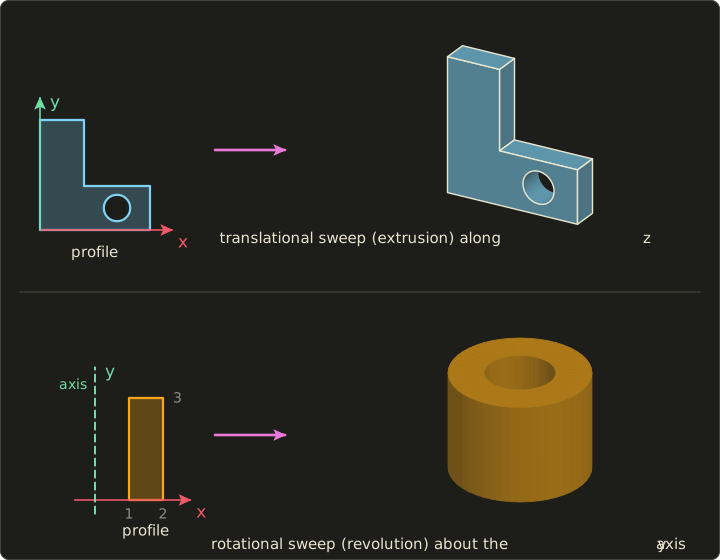
The top row shows that our CSG bracket is also an extrusion: the L-shaped profile with a hole, moved 1 unit along z.
The same solid has more than one representation, and that will be important when we compare them.
Sweeps make volumes easy.
An extrusion's volume is the profile's area times the distance.
For the bracket, the L has area (the two arms minus the square counted twice), the hole , so the volume is .
For a revolution, Pappus's centroid theorem (パップス・ギュルダンの定理) gives the volume as the profile's area times the distance its centroid travels, .
Our rectangle runs from to and from to , so and :
Check it as a difference of two cylinders: .
Sweeps are how designers actually work: "sketch a profile, extrude it" and "sketch half a cross-section, revolve it" are the two most used commands of every CAD program, and a lathe makes exactly rotational sweeps.
Sweeping along a curved path, or sweeping a whole solid (the volume a milling cutter removes as it moves), are generalizations.
The limitation: only shapes with that kind of symmetry can be swept, and as soon as you combine two sweeps you need CSG or B-rep anyway.
Primitive instancing
Primitive instancing (プリミティブインスタンシング) goes one step further than CSG primitives: a whole family of parts is described by a type and a few parameters, such as "hex bolt, M8, length 30" or "spur gear, 24 teeth, module 2".
It's the most compact description possible, and it's how standard-part libraries in CAD work, but it can only describe the families that someone programmed in advance, and you can't combine two instances into a new shape without another representation.
Cell decomposition and spatial occupancy enumeration
Cell decomposition (セル分割表現) glues a solid together from simple cells that don't overlap and only share faces, like building blocks; the bracket without its hole, for example, is the box glued to the box , which touch only along a square.
Its special case with identical cubes on a regular grid is spatial occupancy enumeration (ボクセル表現, voxel representation; literally 空間占有列挙): the solid is the list of grid cells that are inside, the voxels (ボクセル).
Voxels and their adaptive version, the octree (八分木), are the topic of chapter 9, so here only one remark: a voxel model is simple and makes set operations trivial (cell by cell), but it's always an approximation, and its memory grows with the cube of the resolution.
Converting between representations
Since one solid can be described in several ways, CAD systems convert all the time:
- CSG → B-rep (boundary evaluation): intersect the surfaces of the primitives, cut them into pieces, classify each piece as in, on or out of the whole tree, and keep the pieces on the boundary. Hard work, but completely systematic; every CSG-based CAD program does it.
- Sweep → B-rep: easy; the faces of an extrusion are the profile twice plus one side face per profile edge.
- anything → voxels: easy; classify the center of every cell.
- B-rep → CSG: hard and not unique; there are infinitely many trees for the same solid, and finding a good one is a research problem.
- voxels → B-rep: possible as an approximation, with marching cubes (chapter 9).
Comparison
| Representation | What is stored | Strengths | Weaknesses |
|---|---|---|---|
| CSG | primitives and a tree of set operations | compact, always valid, easy to edit, easy inside/outside test | boundary must be evaluated, not unique |
| B-rep | faces, edges, vertices, their connections and geometry | direct access to the boundary (drawing, local operations), used by most CAD | large, validity must be checked |
| Sweep | a profile and a path | very compact, natural for extruded and turned parts | only some shapes |
| Primitive instancing | a type and its parameters | the most compact | only predefined families, can't be combined |
| Cell decomposition, voxels | a list of cells | simple, easy set operations | approximate, memory grows quickly |
Real CAD programs combine them: they keep the CSG-like history of operations the user performed (section 7.7) and a B-rep of the current result.
Exam points
- Wireframe: edges only, ambiguous. Surface: faces, but no inside. Solid: inside defined, so volume, mass and interference checks are possible.
- CSG = primitives + set operations (和・差・積) in a tree; point classification combines in/on/out up the tree.
- Regularized set operations: closure of the interior, ; they remove dangling faces and edges.
- B-rep = faces, edges and vertices with their connections (topology) and their shape (geometry).
- Translational sweep = extrusion, rotational sweep = revolution; CSG → B-rep is routine, B-rep → CSG is hard.
7.4 Topology and geometry
A B-rep stores two kinds of information, and keeping them apart makes everything else in this chapter easier:
- Topology (位相情報) is how the pieces connect: which vertices bound which edge, which edges bound which face, which faces meet at an edge. It's the information that survives if you deform the object like rubber.
- Geometry (幾何情報) is where the pieces are: the coordinates of the vertices and the equations of the edges' curves and the faces' surfaces.
Two quick examples.
Move the vertices of a cube so that it becomes a slanted, stretched box: the geometry changes, but the topology (8 vertices, 12 edges, 6 faces, connected the same way) doesn't, and the data structures of section 7.5 don't change at all.
Now split the cube's front face into two triangles with a diagonal: the shape doesn't change at all, but the topology does (7 faces, 13 edges).
So neither one determines the other, and a B-rep needs both.
Manifold and non-manifold
The boundary of an ordinary solid looks locally like a flat sheet: zoom in on any point of a cube's surface, even on an edge or a corner, and what you see can be flattened into a small disc.
Such a surface is a 2-manifold (2次元多様体, often just 多様体); a solid whose boundary is a 2-manifold is a manifold solid.
For a polygon model this means two concrete rules:
- Every edge belongs to exactly two faces.
- The faces around every vertex form one single fan that closes around the vertex.
A model that breaks them is non-manifold (非多様体):
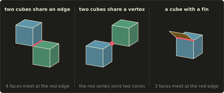
- Two cubes that share only an edge: four faces meet at that edge, breaking rule 1.
- Two cubes that share only a vertex: around that vertex the faces form two separate fans (two cones touching at their tips), breaking rule 2.
- A cube with a fin, a single face hanging off one of its edges: three faces meet at that edge. The fin is exactly the kind of dangling face that regularized set operations remove.
The first two are perfectly reasonable sets of points, and an ordinary union of two cubes can produce them.
They're excluded because the data structures of section 7.5 assume every edge has exactly two sides, and because a 3D printer or a finite element program has no idea what to do with an edge of zero thickness.
(Some CAD kernels support non-manifold models on purpose, for example to mix solids, sheets and wires in one model, but they need richer data structures.)
Orientation and watertightness
Each face of a solid has an outside and an inside.
We record that the way chapter 5 and chapter 6 did: list a face's vertices counter-clockwise when seen from outside, so that the cross product of two consecutive edges gives the outward normal (外向き法線) by the right-hand rule.
This choice is the face's orientation (向き), and it's exactly what back-face culling uses (chapter 6, section 6.4).
For the orientations to be consistent, two neighboring faces must walk their shared edge in opposite directions.
Picture two squares side by side, both counter-clockwise: the left one goes up their common edge, the right one goes down it.
If both went up, one of the two normals would point inwards.
A surface where consistent orientation is impossible is called non-orientable; the famous example is the Möbius strip, which has only one side.
The boundary of a solid always separates inside from outside, so it can always be oriented.
Finally, a surface model is closed or watertight (閉じている, ウォータータイト) if it has no boundary edges, that is, no edges with only one face.
The open box of section 7.1 has four boundary edges around its opening; the cube has none.
These two properties have very practical consequences.
A closed and consistently oriented triangle mesh encloses a volume, and the volume can be computed from the boundary alone: for every triangle add up the signed volume of the tetrahedron it forms with the origin,
(the scalar triple product of Linear Algebra chapter 10, built on the cross product of chapter 5).
Tetrahedra seen from outside the solid count with a minus sign and cancel exactly the parts outside, which only works if the mesh is closed and every face is oriented outwards.
Here it is in C++ with the linalg.hh header of the Linear Algebra series, with the cube stored as an indexed face set (a vertex list plus, per face, the indices of its vertices, which we'll look at in section 7.5):
#include <cstdio>
#include <map>
#include <utility>
#include <vector>
#include "linalg.hh"

// An indexed face set: vertex positions, and for every face its vertex indices,
// counter-clockwise seen from outside.
struct Mesh {
  std::vector<Vec3> v;
  std::vector<std::vector<int>> f;
};

// Volume of a closed, consistently oriented mesh: the sum of the signed volumes of the
// tetrahedra (origin, a, b, c) over a fan of triangles in every face.
float volume(const Mesh &m) {
  float sum = 0;
  for (const auto &face : m.f) {
    for (size_t i = 1; i + 1 < face.size(); ++i) {
      sum += dot(m.v[face[0]], cross(m.v[face[i]], m.v[face[i + 1]]));
    }
  }
  return sum / 6;
}

// Closed and consistently oriented: every directed edge a->b is used by exactly one face,
// and its reverse b->a by exactly one other face.
bool closedAndOriented(const Mesh &m) {
  std::map<std::pair<int, int>, int> count;
  for (const auto &face : m.f) {
    for (size_t i = 0; i < face.size(); ++i) {
      ++count[{face[i], face[(i + 1) % face.size()]}];
    }
  }
  for (const auto &[e, n] : count) {
    auto back = count.find({e.second, e.first});
    if (n != 1 || back == count.end() || back->second != 1) return false;
  }
  return true;
}

int main() {
  Mesh cube{{{0, 0, 0}, {1, 0, 0}, {1, 0, 1}, {0, 0, 1},
             {0, 1, 0}, {1, 1, 0}, {1, 1, 1}, {0, 1, 1}},
            {{0, 1, 2, 3}, {4, 7, 6, 5}, {2, 6, 7, 3}, {0, 4, 5, 1}, {0, 3, 7, 4}, {1, 5, 6, 2}}};
  printf("cube:       volume %g, closed and oriented: %s\n", volume(cube),
         closedAndOriented(cube) ? "yes" : "no");

  Mesh flipped = cube;
  flipped.f[1] = {5, 6, 7, 4}; // the top face listed clockwise
  printf("flipped:    volume %g, closed and oriented: %s\n", volume(flipped),
         closedAndOriented(flipped) ? "yes" : "no");

  Mesh open = cube;
  open.f.erase(open.f.begin() + 1); // no top face
  printf("open box:   volume %g, closed and oriented: %s\n", volume(open),
         closedAndOriented(open) ? "yes" : "no");
  return 0;
}
cube:       volume 1, closed and oriented: yes
flipped:    volume 0.333333, closed and oriented: no
open box:   volume 0.666667, closed and oriented: no
The three faces of the cube through the origin contribute nothing (their tetrahedra are flat), and each of the other three contributes .
Flip one of those and it contributes , so ; remove it and .
Both wrong answers come out without any error message, which is why 3D printing software checks meshes for exactly these two properties ("manifold" and "watertight") before it does anything else.
7.5 Data structures for B-rep
Now let's store a B-rep, using a real solid: the unit cube, with the numbering below.
Vertex for is the bottom square and lies directly above ; the faces are bottom (), top (), front (), back (), left () and right ().
Every edge gets a direction, shown by its arrow.
The coordinates are , , , , and to the same with .
Vertex and face lists (indexed face set)
The simplest structure is the one from the code above: a vertex list (頂点リスト) with the coordinates, and a face list (面リスト) with, for each face, the indices of its vertices counter-clockwise from outside:
| Face | Vertices |
|---|---|
| bottom | 0, 1, 2, 3 |
| top | 4, 7, 6, 5 |
| front | 2, 6, 7, 3 |
| back | 0, 4, 5, 1 |
| left | 0, 3, 7, 4 |
| right | 1, 5, 6, 2 |
Geometry (coordinates) and topology (indices) are cleanly separated, a shared vertex is stored once, and moving it moves all its faces.
This is what file formats and GPUs use (chapter 9 looks at index buffers in detail).
But it can't answer adjacency queries (隣接関係の問い合わせ) quickly: "which faces surround ?" or "which face is on the other side of this edge?" means searching the whole face list.
For 6 faces that's nothing; for a CAD model with a million faces, and an operation that asks such questions millions of times (rounding an edge, smoothing normals, subdividing a surface), it's far too slow.
The next two structures store the neighbors explicitly, so each step of such a walk takes constant time.
The winged-edge structure
The winged-edge structure (ウイングドエッジ構造, also written ウィングドエッジ構造) was introduced by Bruce Baumgart in the 1970s for computer vision and became the classic B-rep structure.
Its idea is to put the connections into the edges.
Each edge record has eight references:
- its two vertices,
startandend(始点, 終点), - its two faces:
left, the face whose counter-clockwise loop walks the edge from start to end, andright, the face that walks it from end to start, - its four wings (ウイング), the neighboring edges in those two loops:
leftPredandleftSucc(the edges just before and after it in the left face's loop) andrightPredandrightSucc(the same in the right face's loop).
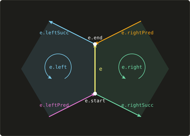
On top of that, every vertex stores one edge that touches it, and every face one edge of its boundary.
The names and the exact choice of wings differ between books (some store clockwise and counter-clockwise successors instead), but every version has those eight references per edge.
Here is the complete table for our cube, computed from the face loops above:
| Edge | start | end | left | right | leftPred | leftSucc | rightPred | rightSucc |
|---|---|---|---|---|---|---|---|---|
Check one row against the picture.
goes up from to .
Walking up it, the front face is on the left and the right face is on the right.
In the front face's loop 2, 6, 7, 3, the edge before arrives at from (that's ) and the edge after it leaves towards (that's ).
Worked lookup 1: the edges of a face.
To walk around face , start at any of its edges , and repeat: if 's left face is , go to leftSucc, otherwise to rightSucc.
For , starting at (whose left face is ):
- : left is , go to its leftSucc .
- : left is , go to .
- : right is , go to its rightSucc .
- : right is , go to : back at the start.
So the right face is bounded by , which visit : exactly the face list's 1, 5, 6, 2.
Worked lookup 2: the faces around a vertex.
This is the query the indexed face set couldn't answer without searching.
Start at the edge that the vertex record stores, and repeat: if the vertex is the edge's start, note the edge's left face and go to leftPred; if it's the edge's end, note the right face and go to rightPred.
(In the face where the edge leaves the vertex, the predecessor is the edge that arrives at the vertex in that same face; crossing it brings us to the next face around the vertex.)
For , whose record stores :
- starts at : face (front), go to leftPred .
- ends at : face (right), go to rightPred .
- ends at : face (top), go to rightPred : back at the start.
The faces around are front, right, top, in counter-clockwise order seen from outside, and the edges around it are .
Three steps for three faces, no search, and the cost of each step doesn't depend on the size of the model.
The half-edge structure
The winged-edge structure has one annoyance: an edge points in only one direction, so every step needs an "is the vertex the start or the end, is the face the left or the right?" test.
The half-edge structure (ハーフエッジ構造) removes it by splitting every edge into two half-edges (ハーフエッジ), one for each face, each pointing in the direction its own face walks it.
A half-edge stores:
origin: the vertex it starts from,twin: the half-edge of the same edge in the neighboring face, pointing the other way,nextandprev: the following and preceding half-edge in its own face's loop,face: the face it belongs to.
Each vertex stores one outgoing half-edge, each face one of its half-edges.
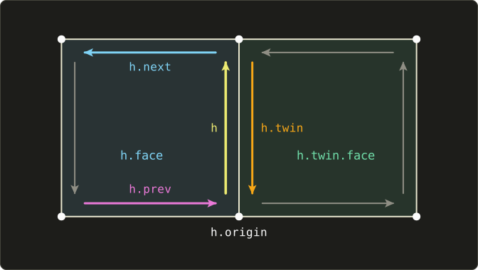
On the cube every edge becomes two half-edges, 24 in all, and since every directed pair of vertices occurs only once, we can name a half-edge by its endpoints: runs from to .
Here are the half-edges we'll need:
| Half-edge | origin | twin | next | prev | face |
|---|---|---|---|---|---|
The traversals become one-liners:
- Around a face: . From : , so the front face is 6, 7, 3, 2.
- Around a vertex: , which goes counter-clockwise seen from outside. From (face ): , its twin is (face ); , its twin is (face ); , its twin is , the start. Faces front, right, top, the same answer as the winged-edge lookup.
- The face across an edge: .
(Going the other way around a vertex is .)
Building a half-edge structure from an indexed face set takes only a few lines: create the half-edges face by face, then find each twin by looking up the reversed vertex pair.
#include <cstdio>
#include <map>
#include <utility>
#include <vector>

struct HalfEdge {
  int origin, twin, next, prev, face;
};

struct HalfEdgeMesh {
  std::vector<HalfEdge> h;
  std::vector<int> vertexEdge; // one outgoing half-edge per vertex
  std::vector<int> faceEdge;   // one half-edge per face
};

// Builds the half-edges of a closed, consistently oriented polygon mesh.
HalfEdgeMesh build(int vertexCount, const std::vector<std::vector<int>> &faces) {
  HalfEdgeMesh m;
  m.vertexEdge.assign(vertexCount, -1);
  std::map<std::pair<int, int>, int> byEnds; // (origin, target) -> half-edge index
  for (int fi = 0; fi < (int)faces.size(); ++fi) {
    const auto &face = faces[fi];
    int first = (int)m.h.size(), n = (int)face.size();
    m.faceEdge.push_back(first);
    for (int i = 0; i < n; ++i) {
      int a = face[i], b = face[(i + 1) % n];
      m.h.push_back({a, -1, first + (i + 1) % n, first + (i + n - 1) % n, fi});
      byEnds[{a, b}] = first + i;
      if (m.vertexEdge[a] < 0) m.vertexEdge[a] = first + i;
    }
  }
  for (const auto &[ends, i] : byEnds) {
    m.h[i].twin = byEnds.at({ends.second, ends.first}); // the same edge, walked the other way
  }
  return m;
}

int main() {
  std::vector<std::vector<int>> faces{{0, 1, 2, 3}, {4, 7, 6, 5}, {2, 6, 7, 3},
                                      {0, 4, 5, 1}, {0, 3, 7, 4}, {1, 5, 6, 2}};
  HalfEdgeMesh m = build(8, faces);

  // faces around vertex 6, counter-clockwise seen from outside: h -> twin(prev(h))
  printf("around v6:");
  int start = m.vertexEdge[6], h = start;
  do {
    const HalfEdge &e = m.h[h];
    printf(" f%d (h%d%d)", e.face, e.origin, m.h[e.next].origin);
    h = m.h[e.prev].twin;
  } while (h != start);
  printf("\n");

  int V = (int)m.vertexEdge.size(), E = (int)m.h.size() / 2, F = (int)m.faceEdge.size();
  printf("V - E + F = %d - %d + %d = %d\n", V, E, F, V - E + F);
  return 0;
}
around v6: f1 (h65) f2 (h67) f5 (h62)
V - E + F = 8 - 12 + 6 = 2
The program's vertex record for happens to be (the first half-edge out of in the face list), so it starts at the top face, but the cycle is the same.
The last line is a preview of section 7.6.
Note that byEnds.at throws if a twin is missing: on an open or non-manifold mesh the structure can't be built as is, which is the price of assuming exactly two faces per edge.
Comparing the three
For the cube, counting references (pointers or indices) without the coordinates:
| Structure | Per item | Cube total |
|---|---|---|
| indexed face set | 4 vertex indices per face | |
| winged-edge | 8 per edge, plus 1 per vertex and per face | |
| half-edge (origin, twin, next, prev, face) | 5 per half-edge, plus 1 per vertex and per face |
The adjacency structures cost four to six times the memory, and that's the trade: an indexed face set is ideal for storing and drawing, while modeling operations, which constantly ask "what's next to this?", need winged-edge or half-edge.
(Dropping prev, which can be found by walking next around the face, brings the half-edge count down to .)
Many mesh-processing libraries (OpenMesh and CGAL, for example) use half-edges; the winged-edge structure is mostly met in textbooks and in exams.
Exam points
- Winged-edge: per edge 2 vertices + 2 faces + 4 wing edges = 8 references; each vertex and face stores one edge.
- Half-edge: origin, twin, next (prev), face; the twin lies in the neighboring face and points the other way.
- Around a face: follow next. Around a vertex: twin of prev (or next of twin). The face across an edge: face of the twin.
- Both assume a manifold: exactly two faces per edge.
7.6 Euler's formula and Euler operators
Euler's formula
Count the vertices V, edges E and faces F of any convex polyhedron and compute :
| Solid | V | E | F | V − E + F |
|---|---|---|---|---|
| tetrahedron | 4 | 6 | 4 | 4 − 6 + 4 = 2 |
| cube | 8 | 12 | 6 | 8 − 12 + 6 = 2 |
| triangular prism | 6 | 9 | 5 | 6 − 9 + 5 = 2 |
| octahedron | 6 | 12 | 8 | 6 − 12 + 8 = 2 |
It's always 2.
That's Euler's formula (オイラーの公式, also called Euler's polyhedron theorem), found by Leonhard Euler in the 18th century:
It holds for every solid whose surface can be blown up into a sphere: no holes through it, no cavities, and every face a disc without holes.
The shape and the size don't matter, which tells you that it's a statement about topology only.
For a modeler it's a cheap sanity check: a B-rep whose counts violate it is certainly broken.
(It's necessary, not sufficient: correct counts don't prove a model is valid, a broken one can have them by accident.)
A useful consequence for triangle meshes: if every face is a triangle, every face has 3 edges and every edge 2 faces, so .
Substituting into Euler's formula gives and : a closed triangle mesh without holes has about twice as many triangles as vertices and three times as many edges.
The octahedron checks out: , , .
The Euler–Poincaré formula
Now drill a square hole through a cube, from the front face to the back face:
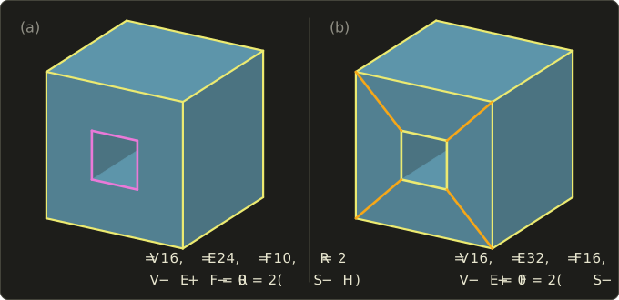
In version (a) the front and back faces are squares with a square hole: each face has an outer boundary and one inner boundary, a ring (リング, an inner loop of a face).
Count: 8 outer and 8 inner vertices, ; 12 outer edges, edges around the two inner squares and 4 along the tunnel, ; 6 cube faces and 4 tunnel walls, .
, which looks fine but is a coincidence, because the formula doesn't apply here.
The general version is the Euler–Poincaré formula (オイラー・ポアンカレの式):
with R the number of rings, S the number of shells (シェル: separate connected boundary surfaces) and H the number of holes (穴) through the solid (its genus, 種数).
For (a): , , :
Version (b) is the same solid with each ring face cut into four trapezoids by four extra edges (orange), so there are no rings: , , , :
And a solid with a cavity: a cube with a smaller cube-shaped empty space inside it has two shells (the outside surface and the cavity's surface), , , , , , :
For a single shell without holes and rings, , , and the formula is Euler's original .
Euler operators
If every valid solid satisfies the formula, why not edit solids only with operations that keep it satisfied?
That's the idea of Euler operators (オイラー操作), introduced by Baumgart and developed into a complete system for solid modelers in the 1980s (Mäntylä's book is the classic reference).
Each operator makes ("M") or kills ("K") a fixed combination of elements:
| Operator | Meaning | ΔV | ΔE | ΔF | ΔR | ΔS | ΔH |
|---|---|---|---|---|---|---|---|
| MVFS | make vertex, face, shell | +1 | 0 | +1 | 0 | +1 | 0 |
| MEV | make edge, vertex | +1 | +1 | 0 | 0 | 0 | 0 |
| MEF | make edge, face | 0 | +1 | +1 | 0 | 0 | 0 |
| KEMR | kill edge, make ring | 0 | −1 | 0 | +1 | 0 | 0 |
| KFMRH | kill face, make ring and hole | 0 | 0 | −1 | +1 | 0 | +1 |
Each has an inverse that undoes it: KVFS, KEV, KEF, MEKR, MFKRH.
(The spellings vary between books: MVFS is also written MVSF or MSFV.)
Check one: MEF changes by and by 0.
KFMRH changes the left side by and the right side by .
Every operator in the table keeps both sides equal, so a model built only from them always satisfies the Euler–Poincaré formula.
Worked example: building a cube.
With the numbering of section 7.5:
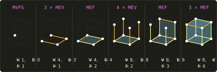
- MVFS creates , together with one face and one shell. A single point already has a "face": the surface around it, which will become two faces when it's split. , , , and .
- 3 × MEV draws the edges and the new vertices : , , , .
- MEF closes the square with and splits the face in two, the bottom and the other side of the square: , , .
- 4 × MEV raises the four vertical edges to with the top vertices to : , , .
- MEF adds from to , cutting off the back face : , , .
- 3 × MEF adds and cuts off , and ; what remains of the original face becomes the top : , , .
Thirteen operators, and after every single one .
That's also a nice way to see why Euler's formula is true: MVFS starts at , and MEV and MEF never change the value.
Worked example: drilling the hole.
Continuing from the cube (scaled to the size of the figure), the through hole of version (a) takes fifteen more operators:
| Step | Operators | V | E | F | R | S | H | V − E + F − R | 2(S − H) |
|---|---|---|---|---|---|---|---|---|---|
| cube | (above) | 8 | 12 | 6 | 0 | 1 | 0 | 2 | 2 |
| a bridge edge from an outer corner into the front face, then the inner square's other three vertices | 4 × MEV | 12 | 16 | 6 | 0 | 1 | 0 | 2 | 2 |
| close the inner square: a new face inside the front face | MEF | 12 | 17 | 7 | 0 | 1 | 0 | 2 | 2 |
| remove the bridge: the inner square becomes a ring of the front face | KEMR | 12 | 16 | 7 | 1 | 1 | 0 | 2 | 2 |
| tunnel edges from the inner square's corners to the back | 4 × MEV | 16 | 20 | 7 | 1 | 1 | 0 | 2 | 2 |
| close the tunnel walls; the inner face is now the bottom of a pocket | 4 × MEF | 16 | 24 | 11 | 1 | 1 | 0 | 2 | 2 |
| the pocket's bottom becomes a ring of the back face: the pocket opens into a hole | KFMRH | 16 | 24 | 10 | 2 | 1 | 1 | 0 | 0 |
At the end we have exactly the numbers of version (a), and the formula held at every step.
Real modelers rarely call Euler operators one by one, but their higher-level operations (extrude, cut, chamfer) are implemented as sequences of them, which guarantees that the topology stays consistent; the geometry (where the new vertices go) is set separately.
Exam points
- Euler: for a solid without holes, cavities or rings. Euler–Poincaré: .
- R counts inner loops of faces, S separate shells (a cavity adds one), H holes through the solid.
- The formula is necessary, not sufficient, for validity.
- Euler operators (MVFS, MEV, MEF, KEMR, KFMRH and their inverses) keep the formula true at every step.
7.7 Local deformation
Local deformation (局所変形) changes a small part of a B-rep without rebuilding it: move one vertex, cut off an edge, round a corner.
Each such operation is a small change of topology (a few Euler operators) plus new geometry.
We'll use the cube and change its front-top-right corner and the top-right edge from to .
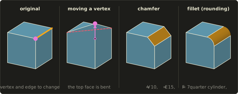
Moving vertices and faces (tweaking)
The simplest local operation, tweaking, only changes geometry: move vertices, keep the topology.
But faces must stay planar, and that's easy to break.
Move the corner up to .
Four points are coplanar exactly when the triple product of the three edge vectors from one of them is zero.
For the top face, , , , :
The top face is no longer planar.
The right face () and the front face () are fine, because the vertex moved along y and stayed in both of their planes (all their x, or all their z, are still 2).
A non-planar face is a real problem: it has no single normal, and different programs would fill it differently.
There are two clean fixes:
- Move the whole face instead of one vertex: lift all four top vertices to , and every face stays planar.
- Split the face with an MEF into two triangles, which are always planar. The topology changes to , , (), and the choice of the diagonal matters: the figure splits along –, which makes a valley (a concave fold), while the other diagonal, through the moved vertex, makes a ridge.
That last point is the topology/geometry split of section 7.4 again: the same eight points, two different solids, depending on one edge.
Chamfering
A chamfer (面取り) cuts off an edge with a plane, replacing the sharp edge by a narrow flat face; machinists do it to remove sharp burrs.
Chamfer the edge from to by : the top face now ends at , the right face at , and the new face has the corners , , , .
Its width is and the removed prism has the volume , leaving .
Topologically, each end of the edge splits into two vertices and one new face appears: , , , and .
As Euler operators: one MEV at each end (splitting the vertex, the new short edge crosses the back or front face) and one MEF that cuts the new face off the right face.
The front and back faces each gained a vertex and became pentagons.
Cutting off a corner instead of an edge gives the same counts, for a different reason: the corner is replaced by a small triangle with 3 vertices (+2), 3 new edges (+3), and 1 new face (+1).
Filleting (rounding)
A fillet or round (丸め, フィレット) replaces the edge by a curved surface that meets both faces smoothly, without a crease.
For our 90° edge and radius , the fillet is a quarter of a cylinder with its axis on the line , , touching the top face along and the right face along .
Its cross-section is a quarter circle of length , a little longer than the chamfer's 0.707, and it removes of volume, less than the chamfer.
The topology is exactly the chamfer's (10, 15, 7); only the geometry differs: the new face is a cylinder instead of a plane, and its edges are a straight line and a circular arc.
That's typical of B-rep: the same local topological operation, with different surface types attached.
Where three rounded edges meet at a corner, the modeler also needs a corner blend, here a piece of a sphere, and blending in general needs the free-form surfaces of chapter 8.
Feature-based modeling and history
Modern mechanical CAD (programs such as SolidWorks, CATIA, NX, Fusion or FreeCAD) doesn't ask the user to think in Euler operators.
The user works with features (フィーチャー): "extrude this sketch 10 mm", "drill a hole of 6 mm here", "fillet these edges with radius 2".
The program records them in a history (履歴, the feature tree), and each feature is executed as B-rep operations by a geometric modeling kernel (commercial kernels such as Parasolid and ACIS, or the open-source Open CASCADE).
Change a number in an early feature and the whole history is replayed, so the part updates; that's parametric, or history-based, modeling.
In a way the history is a CSG tree with more kinds of operations, and the B-rep is its evaluated boundary: the two representations of section 7.3 working together.
One well-known difficulty: if a change upstream alters the topology, a later feature may no longer find "its" edge (the edge it rounded may have been split or may have vanished), which is called the topological naming problem.
For exchange between programs, B-rep solids are saved in neutral formats such as STEP (ISO 10303), while formats like STL store only triangles, a surface model, which is all a 3D printer needs as long as the mesh is closed and oriented.
Exam points
- Tweaking moves vertices or faces without changing topology; a moved vertex can make faces non-planar (check with the triple product).
- Chamfer: a flat face replaces the edge (cube: 10, 15, 7). Fillet: a curved face tangent to both neighbors, same topology as a chamfer.
- Local operations are sequences of Euler operators plus new geometry.
7.8 Summary
- Wireframe models store edges, surface models faces, solid models the inside too; only solids answer volume, mass and interference questions.
- CSG stores primitives combined by union, difference and intersection in a tree; points are classified in/on/out from the leaves up, and the tree can be rendered directly by ray casting.
- Regularized set operations, the closure of the interior, remove dangling faces and edges from the results.
- B-rep stores faces, edges and vertices with their topology (connections) and geometry (positions and surfaces); sweeps, primitive instancing and cell decomposition are other representations, and CAD converts between them.
- A manifold boundary has exactly two faces at every edge and one fan around every vertex; faces are oriented counter-clockwise from outside; a closed, oriented boundary encloses a computable volume.
- Indexed face sets are compact but slow for adjacency; winged-edge stores 8 references per edge; half-edge stores origin, twin, next, prev and face per half-edge, with one-line traversals.
- Euler: ; Euler–Poincaré: ; Euler operators keep it true at every step.
- Local deformation: tweaking (watch planarity), chamfering and filleting; feature-based CAD records operations in a history and replays them on a B-rep kernel.
7.9 Key terms
| English | 日本語 |
|---|---|
| shape model | 形状モデル |
| wireframe model | ワイヤーフレームモデル |
| surface model | サーフェスモデル |
| solid model | ソリッドモデル |
| interference check | 干渉チェック |
| constructive solid geometry (CSG) | CSG表現 |
| primitive | プリミティブ |
| set operation (union, difference, intersection) | 集合演算(和・差・積) |
| CSG tree | CSG木 |
| point membership classification | 点の内外判定 |
| regularized set operation | 正則化集合演算 |
| interior, closure | 内部、閉包 |
| boundary representation (B-rep) | 境界表現(B-rep) |
| boundary evaluation | 境界評価 |
| sweep representation | スイープ表現 |
| translational sweep (extrusion) | 平行移動スイープ(押し出し) |
| rotational sweep (revolution) | 回転スイープ |
| primitive instancing | プリミティブインスタンシング |
| cell decomposition | セル分割表現 |
| spatial occupancy enumeration | ボクセル表現(空間占有列挙) |
| topology, geometry | 位相情報、幾何情報 |
| manifold, non-manifold | 多様体、非多様体 |
| orientation | 向き |
| watertight (closed) | ウォータータイト(閉じている) |
| vertex list, face list (indexed face set) | 頂点リスト、面リスト |
| adjacency | 隣接関係 |
| winged-edge structure | ウイングドエッジ構造 |
| half-edge structure | ハーフエッジ構造 |
| Euler's formula | オイラーの公式 |
| Euler–Poincaré formula | オイラー・ポアンカレの式 |
| ring, shell, hole | リング、シェル、穴 |
| Euler operator | オイラー操作 |
| local deformation | 局所変形 |
| chamfer | 面取り |
| fillet, round | 丸め(フィレット) |
| feature-based modeling | フィーチャーベースモデリング |
7.10 Challenges
- ★ Count V, E and F for a square pyramid, a hexagonal prism and a cube with one corner cut off by a plane, and check Euler's formula for each.
- ★ Classify the points , and against the bracket of section 7.2, writing the in/on/out value of every node of the tree.
- ★★ With the winged-edge table of section 7.5, find the faces around starting from , and the edges of the top face starting from . Check both answers against the picture of the cube.
- ★★ Write a sequence of Euler operators that builds a triangular prism from nothing, with V, E and F after every operator. How many operators do you need, and how does that compare with the cube's 13?
- ★★★ Show that a closed triangle mesh with genus (and one shell, no rings) has faces and edges. How many half-edges per vertex does a half-edge structure need for a large mesh, roughly, and why doesn't the genus matter for that?
Multiple choice
Q1 ★ Which of the following statements about shape models is correct?
| A | A solid model distinguishes the inside from the outside, so it can compute volume and mass and check interference between parts. |
| B | A wireframe model stores the faces of an object, so its volume can be computed. |
| C | A surface model knows which side of each face is inside, so it can always detect interference between two parts. |
| D | A wireframe model always determines a unique solid. |
| E | A surface model cannot contain curved surfaces. |
Q2 ★★ A solid consisting of one shell has 32 vertices, 48 edges and 18 faces, and two of its faces each have three inner loops (rings). How many holes go through it, according to the Euler–Poincaré formula?
| A | These numbers cannot belong to a valid solid. |
| B | |
| C | |
| D | |
| E |
Q3 ★ Which of the following statements about B-rep data structures is correct?
| A | In the half-edge structure, each half-edge stores both faces that share its edge. |
| B | With only a vertex list and a face list, the faces around a vertex can be found in constant time without any search. |
| C | In the winged-edge structure, each edge stores its two vertices, its two faces and four neighboring edges, eight references in all. |
| D | In the half-edge structure, a half-edge and its twin belong to the same face. |
| E | The winged-edge structure can represent an edge shared by three faces without any change. |
7.11 Practical assignment
Model a small house completely by hand: draw it, store it in all the ways of this chapter, check it with Euler's formula, and deform it.
You need graph paper (or isometric paper), a ruler, a pencil, two colored pens and a calculator.
The house is a box with a gable roof whose ridge runs from to .
Its front face () is the pentagon , , , , , and the back face is the same at .
- Draw and number. Draw the house in a parallel projection (an isometric or cabinet view, chapter 5) and number the vertices to : the front pentagon to in the order above, and directly behind . Name the faces (front, back, bottom, left wall, right wall, left roof, right roof).
- Indexed face set. Write the vertex list and the face list, with each face's vertices counter-clockwise seen from outside. For each face, check the orientation with a cross product: the normal must point away from the house.
- Check watertightness and Euler. List every directed edge of every face and check that each edge appears exactly once in each direction. Count V, E, F and check .
- Winged-edge. Give every edge a direction and a name to , and fill in the winged-edge table (start, end, left, right and the four wings) for the five edges of the front pentagon and the ridge edge. Then find the faces around the ridge vertex with the lookup of section 7.5.
- Euler operators. Write a sequence of Euler operators that builds the house (start with the front pentagon), and record V, E and F after every operator.
- Volume. The house is a translational sweep of its front pentagon. Compute the pentagon's area (a square plus a triangle) and the house's volume.
- Deform. (a) Raise the whole ridge to and check with triple products that all faces stay planar. (b) Instead, raise only the front ridge vertex to : which faces become non-planar? (c) Chamfer the ridge edge by moving 0.25 along each roof face from the ridge, and give the new V, E and F.
How to check yourself: in step 3 there must be no edge used twice in the same direction and none used only once; must be 2 after every operator of step 5 and for the final house; in step 4 the faces around must be exactly the three faces you can see meeting at the ridge's front end in your drawing, and the number of faces around a vertex always equals the number of edges around it; the volume in step 6 must lie between the box's 8 and the box plus a full block of the roof's height, 12; and the chamfered house of step 7 (c) must still satisfy Euler's formula.
コメント(0)
まだコメントはありません。
ログインするとコメント出来ます。