13. Rotations and Quaternions
We've been rotating things since chapter 8 with rotateX, rotateY and rotateZ, and in chapter 11 we built a camera from two angles.
That works fine until you need to store an arbitrary orientation, combine many rotations, or blend smoothly from one orientation to another, which is what every animation system does all day.
In this last chapter we'll look at three ways to describe a rotation: Euler angles, axis–angle, and quaternions.
We'll see why the first one causes trouble, how the second one leads to the general rotation matrix, and why the third one, a strange 4D number invented in 1843, is what game engines actually use.
13.1 Euler angles and their problems
The most human way to describe an orientation is with three angles, one per axis.
They're called Euler angles, and for vehicles and cameras the three have names:
| Angle | Axis | Your head does... |
|---|---|---|
| yaw | Y (up) | shaking "no" |
| pitch | X (right) | nodding "yes" |
| roll | Z (forward and back) | tilting towards a shoulder |
In this series we combine them as , the same yaw-after-pitch order as the camera in chapter 11.
Three numbers, easy to type into an editor, easy to understand.
So what's wrong with them?
Problem 1: the order matters
Matrix multiplication isn't commutative (chapter 7), so the same three angles give different orientations in different orders.
Let's rotate by 90° around X and 90° around Y, using the matrices from chapter 8 with and :
X first, then Y. (the vector lies on the X axis, so it doesn't move), then .
Y first, then X. , then .
Same two angles, and the vector ends up pointing into the screen (−Z) in one case and up in the other.
There are 12 possible axis orders and different programs pick different ones, so "yaw 30, pitch 20, roll 10" means nothing until you also say the order.
Problem 2: gimbal lock
Picture the three rotations as three rings nested inside each other, like the gimbal that holds a gyroscope:
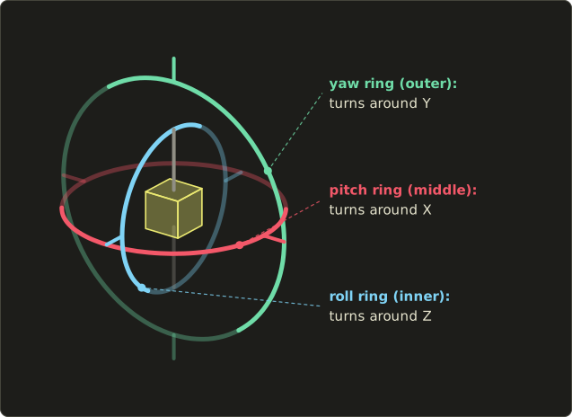
Now pitch up by exactly 90°.
The inner ring's axis, the object's forward and back axis, now points straight up, along the outer ring's Y axis.
Yaw and roll turn around the same line, and there's no ring left that can turn the object around the third direction.
One of the three degrees of freedom is simply gone.
That's gimbal lock.
We can see it in the numbers.
With pitch = 90°, the math works out to , so only the difference yaw − roll matters.
For example (yaw 30°, pitch 90°, roll 0°) and (yaw 50°, pitch 90°, roll 20°) give exactly the same matrix:
Near 90° it's almost as bad: tiny changes of orientation need huge jumps in the angles, and animations swing around wildly.
This isn't just a game problem.
The guidance platform of the Apollo spacecraft used three real gimbals, and the astronauts had to steer clear of gimbal lock.
Michael Collins on Apollo 11 famously joked about asking for a fourth gimbal for Christmas.
Problem 3: interpolation
Say an enemy turns from yaw 170° to yaw −170°.
Those are only 20° apart, through 180°.
But if you blend the angle numbers with lerp (chapter 2), the angle goes 170, 85, 0, −85, −170: a 340° turn the wrong way.
And when all three angles change at once, the blended path is a strange curve instead of the shortest turn.
So Euler angles are great as input (an editor's rotation fields, a first-person camera that never rolls and clamps its pitch), but bad for storing, combining and blending general orientations.
13.2 Axis–angle and Rodrigues' formula
In 1775 Leonhard Euler proved something surprising: any rotation in 3D, or any chain of rotations, is the same as one single rotation around some axis.
So a rotation can be described by a unit vector (the axis) and an angle .
The positive direction follows the right-hand rule: thumb along , fingers curl the way it turns.
The formula
Rodrigues' rotation formula rotates a vector around the unit axis by :
How it works
Split into two parts, using the projection from chapter 4:
- the part along the axis:
- the part perpendicular to the axis:
The part along the axis doesn't move at all, like the axle of a wheel.
The perpendicular part spins around in the plane perpendicular to .
To rotate inside that plane we need two perpendicular directions of the same length, just like and for the 2D rotation in chapter 8.
The first is itself.
The second is : it's perpendicular to both and , and it has the same length as (chapter 5: the length is , and ).
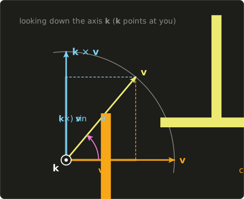
So, exactly like a 2D rotation:
Add the part that didn't move, , and replace with :
With that's Rodrigues' formula.
A worked example
Rotate by 120° around the diagonal .
We need , and .
Now the three terms:
Add them up:
The X axis went to the Y axis.
A 120° turn around the diagonal cycles the axes: x to y, y to z, z to x.
As a matrix
Each of the three terms can be written as a matrix times :
- is times .
- is with the "cross product matrix" below (multiply it out and you get the cross product formula from chapter 5).
- is , where is a 3×1 matrix times a 1×3 matrix, a 3×3 matrix (chapter 7).
So .
With , and , entry by entry:
That's rotate(axis, angle) in linalg.hh, entry for entry.
Quick sanity check: for the Z axis everything with or disappears and the bottom-right entry is , leaving exactly rotateZ from chapter 8.
For the example above every is and every is , so
Its first column, where lands, is , same as before.
Axis–angle is a great way to create a rotation ("spin 30° around this hinge"), and there's no gimbal lock.
But there's no simple formula for combining two axis–angle rotations, and blending them only works nicely when they share an axis.
For that we need quaternions.
13.3 Quaternions: the formula
A bit of history
In the 1830s the Irish mathematician William Rowan Hamilton was trying to multiply 3D points the way complex numbers multiply 2D points.
For years it didn't work.
On 16 October 1843, walking with his wife along the Royal Canal in Dublin, he suddenly saw that he needed four numbers, not three.
He was so excited that he carved the rule into the stone of Brougham Bridge with his knife:
The carving has long worn away, but there's a plaque on the bridge today.
What a quaternion is
No ordinary number squares to −1, so , and are new symbols that simply obey the rule above.
A quaternion is
with four ordinary numbers .
We call the scalar part and the vector part, and we often write .
(These aren't the basis vectors from chapter 2, but they are their ancestors: the letters i, j, k for 3D unit vectors came from Hamilton's quaternions.)
From Hamilton's rule we can work out every product.
For example, take and multiply both sides by on the right: , and since that's , so .
The same kind of steps give the whole table (row times column):
| times | i | j | k |
|---|---|---|---|
| i | −1 | k | −j |
| j | −k | −1 | i |
| k | j | −i | −1 |
Look at it: but .
Quaternion multiplication is not commutative, just like rotations.
It also looks a lot like the cross product: , .
The Hamilton product
Multiplying two quaternions means expanding the brackets and using the table.
If you do that once in general and tidy up, you get a compact form with the dot and cross products:
Written out component by component, this is exactly operator*(Quat, Quat) in the header:
The cross product term is the reason the order matters, because .
Worked example. .
By expanding the brackets with the table:
And with the vector form, and :
Both ways give .
Length, conjugate and inverse
A quaternion's length is the 4D version of chapter 3, and a unit quaternion has length 1:
The conjugate flips the sign of the vector part:
Multiply a quaternion by its conjugate with the vector form: the scalar part is , and the vector part is .
So , and for a unit quaternion that's 1.
In other words, for unit quaternions the conjugate is the inverse, the same way the transpose is the inverse of a rotation matrix (chapter 10), and it's even cheaper: just three sign flips.
13.4 How quaternions rotate vectors
The formula
Unit quaternions are rotations.
The quaternion for a rotation by around the unit axis is
To rotate a vector , write it as a "pure" quaternion and sandwich it:
The vector part of is the rotated vector, and its scalar part always comes out 0.
Why the half angle?
Because is applied twice, once from the left and once from the right.
Let's watch it happen: rotate by 90° around Z.
With (that's and ):
First , with the component formula from the last section:
So : the vector is turned by 45°, only half way.
Now multiply that by on the right:
, so : the other 45°, 90° in total.
Each side did half the work.
(For a vector that isn't perpendicular to the axis, the first multiplication also produces a nonzero scalar part, and the second one cancels it again.
That's why we need the sandwich and not just one multiplication.)
In general, if you expand with , you get Rodrigues' formula from section 13.2, except that shows up as , as and as .
Those are the double-angle identities from trigonometry, so they are the same numbers.
Check them with : and .
The sandwich doubles the angle, so we put in half of it.
13.5 Combining, inverting and converting
Combining rotations
To rotate by first and then by , sandwich twice:
(using , the "socks and shoes" rule again).
So the combined rotation is the single quaternion , read right to left, exactly like matrices.
Worked example. First 90° around X, then 90° around Y, the "X first" case from section 13.1.
With :
So .
What rotation is that?
means , so , and the axis is the vector part divided by , which is .
Two 90° turns combine into one 120° turn around a diagonal, just as Euler's theorem promised.
Rotating with it gives , the same answer as the matrices in section 13.1.
Inverse and the double cover
The inverse of a unit quaternion is its conjugate: turns by the same angle the other way.
Something odd: and are the same rotation.
In the two minus signs cancel.
You can also see it from the half angle: turning by is the same rotation as turning by , but (and the same for sin), which flips the sign of all four numbers.
So every rotation has exactly two quaternions, a property called the double cover.
It matters for interpolation, as we'll see in a moment.
To a matrix
GPUs want matrices.
The columns of a rotation matrix are where , and land (chapter 6), so rotate each of them with and simplify using .
The result is toMat4 in the header:
It assumes a unit quaternion.
Worked example. Our 120° rotation around from section 13.2 as a quaternion is .
Every product of two components is , so:
The same matrix Rodrigues gave us.
Since every entry multiplies two components, gives the same matrix too, which is the double cover again.
Renormalizing
Every multiplication rounds a little (floats only have about 7 digits).
If you update an orientation every frame with q = step * q, those errors pile up and the length slowly drifts away from 1.
A quaternion that isn't unit length no longer just rotates: toMat4 will also start to squash or stretch the object.
The fix is cheap: call normalize(q) after updating it (four divisions and one square root).
With a 3×3 rotation matrix the same drift makes the columns stop being perpendicular, and repairing that needs several cross products.
That cheap repair is one more reason engines store orientations as quaternions.
13.6 Interpolation: lerp, nlerp and slerp
Animation needs to go smoothly from orientation to orientation as goes from 0 to 1.
Think of unit quaternions as points on a sphere in 4D: we want to walk along the sphere from to .
lerp. Blend the four numbers (chapter 2): .
This cuts straight through the inside of the sphere, so the result is shorter than 1 in the middle.
Halfway between "no rotation" and "180° around Y" you get , with length 0.7071.
Not a rotation any more.
nlerp. Normalize the lerp: .
Now it's on the sphere and it follows the shortest path, so it's often good enough.
But it doesn't move at a constant speed: slower at the ends, faster in the middle.
slerp ("spherical linear interpolation") walks along the sphere at constant speed.
Let be the angle between and in 4D, found with the 4D dot product (chapter 4): .
Then
The header's slerp adds two important details:
- Short path. If , it negates . Because of the double cover, is the same rotation, but it's on the near side of the sphere. Without this, blending from 0° to 350° would swing 350° the long way instead of 10° the short way.
- Near-parallel fallback. If , then is almost 0 and so is , and dividing by it would blow up. When the two are that close, nlerp gives practically the same result, so it uses that.
Worked example. From no rotation to 90° around Y, , halfway.
, so .
(The 4D angle is half the rotation angle, the half angle again.)
At both weights are equal:
And is a 45° rotation around Y, exactly half of 90°.
slerp vs nlerp. Here's the rotation angle from no rotation to 180° around Y:
| t | slerp | nlerp | length of plain lerp |
|---|---|---|---|
| 0 | 0° | 0° | 1 |
| 0.25 | 45° | 36.87° | 0.7906 |
| 0.5 | 90° | 90° | 0.7071 |
| 0.75 | 135° | 143.13° | 0.7906 |
| 1 | 180° | 180° | 1 |
slerp moves evenly.
nlerp lags behind in the first half and runs ahead in the second half, but it ends up in the same places at 0, 0.5 and 1.
For small steps (like between two animation keyframes) the difference is tiny.
The short path in numbers. A turn of 350° around Y is .
Then , so slerp uses instead, which is a turn of −10°.
Halfway it's at −5°, the short way round, as you'd want.
13.7 Use in graphics programming
- Skeletal animation. Each bone's keyframes store a rotation as a quaternion (next to a translation and a scale). To play the animation, the engine finds the two keys around the current time and slerps or nlerps between them. Blending a walk into a run is the same thing with a blend weight. Many engines use nlerp here, because it's cheaper and the keys are close together.
- Smooth turning. A camera or a turret can turn towards a target orientation a little each frame with
current = slerp(current, target, amount), with no gimbal lock and always along the shortest arc. - Physics engines store each rigid body's orientation as a quaternion. With the angular velocity (in world space, radians per second) one step is , followed by a
normalize. - Networking. A unit quaternion has four numbers but only three are needed: since you can rebuild the fourth. A popular scheme, "smallest three", sends the index of the largest component in 2 bits plus the other three. Thanks to the double cover the sender can flip the sign so the dropped component is always positive.
Why shaders usually get matrices. The vertex shader already multiplies by a 4×4 matrix that contains translation, scale and projection too, and rotating with a matrix costs fewer operations than with a quaternion.
So the usual plan is: keep orientations as quaternions on the CPU, convert once per object with toMat4, build the model matrix, and send matrices.
Quaternions do show up in shaders when memory matters, for example per-instance orientations in a huge instance buffer, or compact skinning data.
Here's the standard shader function.
It's expanded and simplified to two cross products: , where is the vector part.
// q = float4(x, y, z, w): xyz is the vector part, w is the scalar part
float3 rotateByQuat(float4 q, float3 v) {
  return v + 2.0 * cross(q.xyz, cross(q.xyz, v) + q.w * v);
}
// q = vec4(x, y, z, w): xyz is the vector part, w is the scalar part
vec3 rotateByQuat(vec4 q, vec3 v) {
return v + 2.0 * cross(q.xyz, cross(q.xyz, v) + q.w * v);
}// q = float4(x, y, z, w): xyz is the vector part, w is the scalar part
float3 rotateByQuat(float4 q, float3 v) {
return v + 2.0 * cross(q.xyz, cross(q.xyz, v) + q.w * v);
}
Watch the storage order. In the shader the quaternion is a float4 / vec4 stored as (x, y, z, w), so that q.xyz is the vector part and q.w the scalar part.
Our C++ Quat is declared as (w, x, y, z).
So when you upload one, reorder it:
float gpuQuat[4] = {q.x, q.y, q.z, q.w}; // shader order: x, y, z, wForget it and the identity is read as , : a 180° turn around X, and your whole model is upside down.
13.8 Other uses
- Spacecraft. Attitude control software on satellites and space stations represents orientation with quaternions, and star trackers report the spacecraft's attitude as a quaternion. No gimbal lock, and cheap to renormalize, both important when a computer runs for years without a reboot.
- Drones and phones. IMU sensor fusion algorithms (like the Madgwick and Mahony filters) combine the gyroscope, accelerometer and magnetometer into an orientation quaternion. Android's rotation vector sensor reports the components of a unit quaternion.
- VR. OpenXR reports the pose of the headset and each controller as a position plus an orientation quaternion, every frame.
- Robotics. ROS messages store orientations as quaternions, in (x, y, z, w) order like our shaders.
- Molecular modeling. Docking simulations rotate molecules around constantly, and finding the best rotation to overlay two molecules has an elegant quaternion solution.
- 3D software. Blender lets you switch each object or bone between Euler and quaternion rotation modes, exactly for the reasons in this chapter.
13.9 Code
Here is the rotation part of linalg.hh: rotate(axis, angle) from section 13.2, then everything for quaternions.
Notice Quat's defaults: w = 1 and the rest 0, so Quat{} is "no rotation".
fromAxisAngle normalizes the axis for you and uses the half angle.
// 任意軸周りの回転(ロドリゲスの回転公式) / rotation around any unit axis (Rodrigues) (chapter 13)
inline Mat4 rotate(Vec3 axis, float angle) {
  Vec3 a = normalize(axis);
  float c = std::cos(angle), s = std::sin(angle), t = 1.0f - c;
  Mat4 m = Mat4::identity();
  m.at(0, 0) = t * a.x * a.x + c;
  m.at(0, 1) = t * a.x * a.y - s * a.z;
  m.at(0, 2) = t * a.x * a.z + s * a.y;
  m.at(1, 0) = t * a.x * a.y + s * a.z;
  m.at(1, 1) = t * a.y * a.y + c;
  m.at(1, 2) = t * a.y * a.z - s * a.x;
  m.at(2, 0) = t * a.x * a.z - s * a.y;
  m.at(2, 1) = t * a.y * a.z + s * a.x;
  m.at(2, 2) = t * a.z * a.z + c;
  return m;
}

// q = w + xi + yj + zk
struct Quat {
  float w = 1.0f, x = 0.0f, y = 0.0f, z = 0.0f;

  // 単位軸axis周りにangleラジアン回転 / rotation of angle radians around a unit axis
  static Quat fromAxisAngle(Vec3 axis, float angle) {
    Vec3 a = normalize(axis);
    float s = std::sin(angle * 0.5f);
    return {std::cos(angle * 0.5f), a.x * s, a.y * s, a.z * s};
  }
};

// ハミルトン積 / Hamilton product
inline Quat operator*(Quat a, Quat b) {
  return {
    a.w * b.w - a.x * b.x - a.y * b.y - a.z * b.z,
    a.w * b.x + a.x * b.w + a.y * b.z - a.z * b.y,
    a.w * b.y - a.x * b.z + a.y * b.w + a.z * b.x,
    a.w * b.z + a.x * b.y - a.y * b.x + a.z * b.w,
  };
}

inline Quat conjugate(Quat q) { return {q.w, -q.x, -q.y, -q.z}; }

inline Quat normalize(Quat q) {
  float len = std::sqrt(q.w * q.w + q.x * q.x + q.y * q.y + q.z * q.z);
  return {q.w / len, q.x / len, q.y / len, q.z / len};
}

// ベクトルを回転:v' = q v q* / rotate a vector: v' = q v q*
inline Vec3 rotate(Quat q, Vec3 v) {
  Quat p{0.0f, v.x, v.y, v.z};
  Quat r = q * p * conjugate(q);
  return {r.x, r.y, r.z};
}

// 単位クォータニオンから回転行列へ / unit quaternion to rotation matrix
inline Mat4 toMat4(Quat q) {
  float w = q.w, x = q.x, y = q.y, z = q.z;
  Mat4 m = Mat4::identity();
  m.at(0, 0) = 1 - 2 * (y * y + z * z);
  m.at(0, 1) = 2 * (x * y - w * z);
  m.at(0, 2) = 2 * (x * z + w * y);
  m.at(1, 0) = 2 * (x * y + w * z);
  m.at(1, 1) = 1 - 2 * (x * x + z * z);
  m.at(1, 2) = 2 * (y * z - w * x);
  m.at(2, 0) = 2 * (x * z - w * y);
  m.at(2, 1) = 2 * (y * z + w * x);
  m.at(2, 2) = 1 - 2 * (x * x + y * y);
  return m;
}

// 球面線型補間 / spherical linear interpolation
inline Quat slerp(Quat a, Quat b, float t) {
  float d = a.w * b.w + a.x * b.x + a.y * b.y + a.z * b.z;
  if (d < 0.0f) { // 短い方の道を選ぶ / take the shorter path
    b = {-b.w, -b.x, -b.y, -b.z};
    d = -d;
  }
  if (d > 0.9995f) { // ほぼ同じ向き:線型補間で十分 / nearly equal: plain lerp is enough
    Quat r{a.w + t * (b.w - a.w), a.x + t * (b.x - a.x), a.y + t * (b.y - a.y), a.z + t * (b.z - a.z)};
    return normalize(r);
  }
  float theta = std::acos(d);
  float sa = std::sin((1.0f - t) * theta) / std::sin(theta);
  float sb = std::sin(t * theta) / std::sin(theta);
  return {sa * a.w + sb * b.w, sa * a.x + sb * b.x, sa * a.y + sb * b.y, sa * a.z + sb * b.z};
}
Like normalize(Vec3) in chapter 3, normalize(Quat) can't fix a zero quaternion (it would divide by zero), but a rotation quaternion is never zero, so that's fine.
And the test program.
It reproduces this chapter's worked examples, compares the quaternion against Rodrigues' matrix for an awkward axis and angle, and shows the drift from section 13.5.
#include <cstdio>
#include "linalg.hh"

static void printQuat(const char *name, Quat q) {
  printf("%-8s (w %.4f, x %.4f, y %.4f, z %.4f)\n", name, q.w, q.x, q.y, q.z);
}

static void printVec(const char *name, Vec3 v) {
  printf("%-8s (%.4f, %.4f, %.4f)\n", name, v.x, v.y, v.z);
}

int main() {
  // 120 degrees around (1, 1, 1): x -> y -> z -> x
  Quat q = Quat::fromAxisAngle({1, 1, 1}, radians(120.0f));
  printQuat("q", q);
  printVec("q x", rotate(q, Vec3{1, 0, 0}));

  // compare with Rodrigues' matrix for a less friendly axis and angle
  Vec3 axis{1, 2, 3};
  float angle = 0.7f;
  Vec3 v{0.3f, -1.0f, 2.0f};
  Mat4 r = rotate(axis, angle);
  Vec4 a = r * Vec4{v.x, v.y, v.z, 0.0f};
  Vec3 b = rotate(Quat::fromAxisAngle(axis, angle), v);
  printVec("matrix", {a.x, a.y, a.z});
  printVec("quat", b);

  Mat4 m = toMat4(Quat::fromAxisAngle(axis, angle));
  float maxDiff = 0.0f;
  for (int row = 0; row < 4; ++row)
    for (int col = 0; col < 4; ++col)
      maxDiff = std::fmax(maxDiff, std::fabs(m.at(row, col) - r.at(row, col)));
  printf("toMat4 == rotate: %s\n", maxDiff < 1e-5f ? "yes" : "no");

  // combining: first 90 degrees around X, then 90 degrees around Y
  Quat q1 = Quat::fromAxisAngle({1, 0, 0}, radians(90.0f));
  Quat q2 = Quat::fromAxisAngle({0, 1, 0}, radians(90.0f));
  Quat both = q2 * q1;
  printQuat("q2*q1", both);
  printVec("x", rotate(both, Vec3{1, 0, 0}));

  // slerp halfway from "no rotation" to 90 degrees around Y
  Quat half = slerp(Quat{}, q2, 0.5f);
  printQuat("half", half);
  printf("angle    %.1f degrees\n", degrees(2.0f * std::acos(half.w)));

  // drift: apply a tiny rotation a million times
  Quat step = Quat::fromAxisAngle({0, 1, 0}, 0.001f);
  Quat drift{}, fixed{};
  for (int i = 0; i < 1000000; ++i) {
    drift = step * drift;
    fixed = normalize(step * fixed);
  }
  auto len = [](Quat x) { return std::sqrt(x.w * x.w + x.x * x.x + x.y * x.y + x.z * x.z); };
  printf("length without normalize %.6f, with %.6f\n", len(drift), len(fixed));
  return 0;
}
Expected output:
q        (w 0.5000, x 0.5000, y 0.5000, z 0.5000)
q x      (-0.0000, 1.0000, 0.0000)
matrix   (1.5069, -0.8098, 1.4709)
quat     (1.5069, -0.8098, 1.4709)
toMat4 == rotate: yes
q2*q1    (w 0.5000, x 0.5000, y 0.5000, z -0.5000)
x        (0.0000, 0.0000, -1.0000)
half     (w 0.9239, x 0.0000, y 0.3827, z 0.0000)
angle    45.0 degrees
length without normalize 1.002127, with 1.000000
The quaternion for 120° around is as in section 13.5, the combined rotation is , and slerp halfway gives the 45° rotation from section 13.6.
The exact digits of the drift line depend on your compiler and CPU, but without normalize the length always creeps away from 1.
(The -0.0000 is a negative zero again, see chapter 11.)
13.10 Looking back, looking forward
That's the end of the series.
Let's look at how far we've come.
We started with arrows and lists of numbers (chapter 2), measured them (chapter 3), and learned the two products that answer "how much in the same direction?" and "which direction is perpendicular?" (chapters 4 and 5).
We packed linear combinations into matrices (chapters 6 and 7), used them to scale, rotate, shear and mirror (chapter 8), added a fourth coordinate so we could move things too (chapter 9), and learned to undo all of it (chapter 10).
Then we put a camera in the world (chapter 11), flattened the world onto the screen (chapter 12), and finally found a better way to handle rotations (this chapter).
Now look at the heart of every vertex shader:
float4 toClip(float4x4 proj, float4x4 view, float4x4 model, float3 position) {
  return mul(proj, mul(view, mul(model, float4(position, 1.0))));
}
vec4 toClip(mat4 proj, mat4 view, mat4 model, vec3 position) {
return proj * view * model * vec4(position, 1.0);
}float4 toClip(float4x4 proj, float4x4 view, float4x4 model, float3 position) {
return mul(proj, mul(view, mul(model, float4(position, 1.0))));
}
Every chapter is in it: vectors, a homogeneous coordinate w = 1, three matrix products applied right to left, a model matrix built from scale, a quaternion turned into a rotation, and a translation, a view matrix from lookAt, and a projection that sets up the perspective divide.
Before this series, that one line was magic.
Now you can calculate it by hand.
Next come the Slang, GLSL, Vulkan and OpenGL series, where we'll put all of this on the GPU: uploading these matrices from C++, lighting with dot products and normals, cameras, shadow maps, and skinned characters.
Keep your linalg.hh around, we'll be using it there.
Thanks for reading all the way to the end!
13.11 Summary
- Euler angles (yaw, pitch, roll) are easy for humans but depend on the order, suffer from gimbal lock (at pitch 90° yaw and roll turn around the same axis), and interpolate badly.
- Any rotation is one turn by around a unit axis . Rodrigues' formula rotates a vector, and its matrix is
rotate(axis, angle). - A quaternion is with . The Hamilton product is and isn't commutative.
- A rotation by around is , applied as . The half angle is there because the sandwich applies twice.
- means "first , then ". For unit quaternions the conjugate is the inverse. and are the same rotation.
toMat4converts to a matrix for the GPU. Normalize regularly to fight rounding drift.- lerp leaves the unit sphere, nlerp is cheap but uneven, slerp is even. slerp flips when and falls back to nlerp when .
- Shaders store quaternions as (x, y, z, w), while our C++
Quatis (w, x, y, z).
13.12 Challenges
- ★ Compute and by hand, once with the multiplication table and once with the vector form of the Hamilton product. Which part of the answer changes when you swap the order, and why?
- ★ Write down the unit quaternion for 180° around the X axis, and rotate with by hand. Does the answer match what
rotateXfrom chapter 8 would do? - ★ Use Rodrigues' formula to rotate by 90° around . Check your answer with the
rotateZmatrix. - ★ Find the rotation axis and angle of . Then compute
toMat4of and confirm it's the same matrix as for . - ★★ Write
Quat nlerp(Quat a, Quat b, float t)with the same short-path flip asslerp. BetweenQuat{}and 180° around Y, print the rotation angle in degrees for t = 0, 0.25, 0.5, 0.75 and 1. You should get 0, 36.87, 90, 143.13 and 180, whileslerpgives 0, 45, 90, 135 and 180. - ★★ Write
Quat fromEuler(float yaw, float pitch, float roll)as the product of threefromAxisAnglequaternions in the order Y, X, Z, and check that itstoMat4equals the product ofrotateY(yaw),rotateX(pitch)androtateZ(roll)in that order. Then show gimbal lock in numbers: (30°, 90°, 0°) and (50°, 90°, 20°) should both print the quaternion . - ★★★ Using the vector form of the Hamilton product, show that the scalar part of is always 0 for a pure quaternion and a unit quaternion . Then explain why is exactly what makes " means first" work.
コメント(0)
まだコメントはありません。
ログインするとコメント出来ます。